Quantcast
Channel: Brezular's Blog
Viewing all 151 articles
Browse latest View live

Enterprise Network on GNS3 - Part 1 - Introduction

$
0
0

Several months ago I had created a simple GNS3 network topology for practicing my networking skills. What had firstly begun as a simple lab, later grew in to a real world enterprise network consisting of a campus, data center, DMZ network blocks and ISPs. During the next several weeks I added new devices into the topology, struggling with no time due to complicated family circumstances. In March 2017 I completely stopped working on this project. Luckily, I was done with the configuration of all devices and I wrote several articles describing my progress. Now, almost a half of the year later, I am ready to share my experience with the blog readers and publish the articles. Below is the list of the articles. I hope you find them useful.

Enterprise Network on GNS3 - Part 1 - Introduction
Enterprise Network on GNS3 - Part 2 - Access Layer
Enterprise Network on GNS3 - Part 3 - Distribution and Core Layers
Enterprise Network on GNS3 - Part 4 - Cisco ASAv-I
Enterprise Network on GNS3 - Part 5 - Data Center
Enterprise Network on GNS3 - Part 6 - Edge Router and ISPs
Enterprise Network on GNS3 - Part 7 - DMZ

The name of the enterprise is CompanyXYZ. The complete enterprise network topology is shown on the picture below. As I have mentioned, it composes of the campus network, data center (DC), DMZ and ISPs.

Picture 1 - Enterprise Network Running On Laptop with GNS3

The entire topology is virtualized, running on the ASUS K55VM laptop with the following hardware and software specification:

Host Hardware:
1. CPU: Intel(R) Core(TM) i7-3610QM CPU @ 2.30GHz
2. RAM: 16GB: 2x Kingston 8192 MB DDR3, speed 1600Mhz
3. Ethernet card: RTL8111/8168/8411 PCI Express Gigabit Ethernet Controller

Host Software:
1. OS: Ubuntu 16.04.2 LTS Xenial
2. GNS3: version 1.5.3
3. QEMU emulator and KVM: version 2.8.0
4. Dynamips emulator: version 0.2.16

The enterprise campus network consists of the access, distribution and core layers. The data center is composed of the layer 3 Cisco switch and the server. The design of the DC is very simplified as the network tiers are squeezed to a single switch layer 3 switch. Unlike the campus network, the aim is to show configuration of the services running on the Server1 instead of discussing the complete DC design. The company edge router is connected to the Internet using two Internet Service Providers (ISPs). The Cisco ASA firewall connects a campus network, data Center and the edge router. The edge router connected DMZ to the rest of the enterprise network and to the Internet. The DMZ consists of the Cisco ASA firewall, layer 3 Cisco switch and the DMZ server. The enterprise is connected to the ISP1 and ISP2 routers via enterprise edge router. Both ISP routers  are bridged via GNS3 clouds to the laptop Ethernet Card RTL8168 (enp4s0f2) in order to simulate connection to the Internet.

Now we can spend few words about devices in enterprise network and software they are running .

Enterprise Campus Network
1. PC1 - PC4: Linux Core 6.3, kernel 3.16.6
2. Access switches: OpenSwitch 0.4.0 (Linux core-4.1-noarch:core-4.1-x86_64)
3. Distribution switches: Arista vEOS, version 4.17.2F
4. Core switches: Cisco vIOS l2 software, vios_l2-ADVENTERPRISEK9-M, version 15.2

Firewall ASAv-I: Cisco Adaptive Security Appliance Software Version 9.6(1)

Data Center:
1. Server: Ubuntu 16.04.3 LTS (GNU/Linux 4.4.0-92-generic x86_64)
2. Switch: Cisco vIOS l2 software, vios_l2-ADVENTERPRISEK9-M, version 15.2

Edge Router: Cisco IOSv software, VIOS-ADVENTERPRISEK9-M, version 15.6(2)T,

DMZ:
1. Firewall: Cisco Adaptive Security Appliance Software Version 9.6(1)
2. Switch: Cisco vIOS l2 Software, vios_l2-ADVENTERPRISEK9-M, version 15.2
3. Server: Ubuntu 16.04.3 LTS (GNU/Linux 4.4.0-92-generic x86_64)

ISPs: Cisco 7206VXR (NPE400), Cisco IOS Software, 7200 Software (C7200-ADVIPSERVICESK9-M), version 15.2(4)S4

Public IP Addresses Assignment
The company has assigned a block of the public IP addresses 195.1.1.0/24. This is the entire class C network. The first a half of the IP addresses range is used for NAT and the second half of the range is used for DMZ. Below is the complete list of  used subnets and their assignment.

195.1.1.0/25 - NAT
- 195.1.1.128/25 - DMZ
--- 195.1.1.128/32 - point-to-point connection - in use
--- 195.1.1.132/32 - point-to-point connection - in use
--- 195.1.1.136/32 - point-to-point connection - free
--- 195.1.1.140/32 - point-to-point connection - free
--- 195.1.1.144/32 - point-to-point connection - free
--- 195.1.1.148/32 - point-to-point connection - free
--- 195.1.1.152/32 - point-to-point connection - free
--- 195.1.1.156/32 - point-to-point connection - free
--- 195.1.1.160/29 - Vlan 10 - in use
--- 195.1.1.192/29 - free
--- 195.1.1.224/29 - free

Note: The router vIOS-EDGE-I has assigned a public IP address 198.10.10.2 from the ISP1 IP address range and the IP address 197.10.10.2 from ISP2 IP address range.

Private IP Addresses Assignment
Users connected to the ports of the access switches have their IP addresses assigned from the networks 192.168.10-40.0/24. Point-to-points links between Distribution and Core switches are configured with IP addresses from the subnets 10.0.0.0/24. Point-to-point links between ASAv-I, campus network and data center are configured with IP addresses from the subnet 172.16.0.0/24. The server Server1 is connected to the Cisco L3 switch vIOS-Ser-I in a DC and it has IP address assigned from the subnet 172.16.50.0/24. Loopback and management IP addresses are assigned from the subnet 10.1.1.0/24.

Users: 192.168.10-40.0/24
Distribution and core layer links: 10.0.0.0/24
ASAv-I, campus and data center links: 172.16.0.0/24
Server1 (DC): 17.16.50.0/24
Loopbacks: 10.1.1.0/24 and management

Services Provided by Servers
Servers Server1 in a DC and the SERV-DMZ-I in DMZ provide the following services.

1. DNS: Domain name resolution for network devices and workstations
2. DHCP: automatic IP address assigment for workstations
3. Syslog: logging for network devices
4. NTP: precise time for network devices
5. Radius: remote authentication for network devices (except DMZ and vIOS-EDGE-I)
6. Web: company WEB server for Internet users (only DMZ)

Interfaces Naming
Each network interface in the topology has assigned two interface names although the both names represent a single interface. The first name is assigned by GNS3 itself (e0, e1, e2 etc.). The second name is the interface name that is shown in the configuration of the device. For instance, the ASAv-I is connected with the vIOS-Core-II with the interface e1. However, the interface e1 is represented by the interface Gi0/0 in the ASA configuration.

Login Credentials
Below is the list of the changed usernames and passwords for all devices in the topology. The string before the slash represents a username and the string after the slash represents the password.

1. Local Credentials for Cisco and Arista Devices

Local User  - Level 1
admin/cisco

Local User -  Level 15
admin15/cisco15

Local Enable
cisco

2. Radius Credentials for Cisco and Arista Devices

Radius User - Level 1
raadmin/racisco

Radius User - Level 15
raadmin15/racisco15

Radius Enable
racisco

3. Local Credentials for Openswitch Appliance

netop/cisco
Linux: admin/cisco

4. Credentials for PC1 - PC4:   tc/tc

5. Credentials for Linux Ubuntu:  ubuntu/ubuntu

6. ISP1 and ISP2:  devices are not configured for authentication.

Bandwidth Limitation
Cisco ASAv is unlicensed so the traffic rate is limited to 100 kbps and maximum connection limit is set to 100. For this reason, connection to the Internet is limited to 100 kbps.

Issues
I noticed some mysterious issues while running the devices that I could not explain. Luckily, very often restarting a port for a particular device solved a problem. For instance, network traffic originated on ISP1 was sent to the Internet from the Gi0/0. However, the router ISP1 did not forward incoming data traffic to the Internet that entered the interface Gi0/1. In this case, restart of the port Gi0/0 on the ISP1 solved the issue. The other issue that I noticed was about 2% loss of the packets destined for the Internet when both ISP routers were running simultaneously. If the both routers were not needed to run at the same time, shutdown of the ISP2 router represented a workaround. As the last point, I recommend to use vIOS-l2 instead of the OpenSwitch appliances as I have spent hours troubleshooting OpenSwitch unexpected behavior. As I have mentioned, very often temporary shutdown of VLAN or VLAN interface solved a mystery.


Enterprise Network on GNS3 - Part 2 - Access Layer

$
0
0

This is the second from the series of the articles that discuss a complete configuration of the enterprise network. Our enterprise campus network consists of the core, distribution and access layer. This network infrastructure design is called a three-tier network model. Each layer has specific function. The access layer provides access for end users to the network . They are two access switches located inside the access layer. The access switches OpenSwitch-Acc-I and OpenSwitch-Acc-II are OpenSwitch Qemu appliances installed on VMware VMDK disks. The switches run OpenSwitch network OS version 0.4.0 and they have assigned 1024 MB memory by GNS3. More details about building OpenSwitch appliance prior to version 2.0 can be found here.

The ports Ethernet 3 a and 4 on both switches are configured as access ports and they connect PC1 and PC4 to the campus network. The ports Ethernet 1 and Ethernet 2 are uplinks that connect access switches to the distribution switches. They are configured as trunk ports, carrying traffic from multiple VLANs. Thanks to redundant uplink connection, the access switches remain connected to the upper layer, even in case of the failure one of the distribution switches.

Picture 1 - Access Switches Connected to Distribution Layer

End user computers are assigned to VLANs 10, 20, 30 and 40. Thanks to segmentation to VLAN, user traffic is sent to the distribution layer without being spread across the other access switches in campus. The PC4 is connected to the port Ethernet 4 that is assigned to the management VLAN 40. Management of the access switches is provided by connection of the management port Ethernet0 to the port Ethernet6 of the particular distribution switch. The both ports are configured as the routed (layer3) ports and they have assigned IP addresses from the subnet with /30 mask.

The Switch Virtual Onterface (SVI) created on both access switches allow the access switches to synchronize their time with NTP server running on the appliance Server1 172.16.50.1 in the Data Center (DC). The switches also send logs to the syslog-ng server installed on the same appliance.

Note: The configuration files of the both access switches are: OpeSwitch-Acc-I and OpenSwitch-Acc-II.

1. OpenSwitch-Acc-I Configuration

Login to the OpenSwitch OpenSwitch-Acc-I appliance with the default username netop and the password netop. As a first step, we will change the hostname.

switch# conf t
switch(config)# hostname OpenSwitch-Acc-I

1.1 VLANs Configuration

The VLANs 10,20 are end user VLANs. The VLAN 999 is "parking" VLAN that is configured on ports that are not used. If someone accidentally brings disabled switchports up, the connection is not working. It is because the VLAN 999 is not configured on uplink trunk ports.

OpenSwitch-Acc-I(config)# vlan 10
OpenSwitch-Acc-I(config-vlan)# no shutdown
OpenSwitch-Acc-I(config)# vlan 20
OpenSwitch-Acc-I(configb-vlan)# no shutdown
OpenSwitch-Acc-I(config)# vlan 999
OpenSwitch-Acc-I(config-vlan)# no shutdown
OpenSwitch-Acc-I(config-vlan)# exit

Note: If you encounter strange connectivity problem that you cannot troubleshoot, restart of the particular VLAN might help.

1.2 IP Address and Trunk Port Configuration

In order to access the switches remotely, we have to configure the appropriate IP address and mask on the management port. The management port mgmt is the only interface that is presented in underlying Linux Yocto Linux (except the loopback). However it can by comfortably configured using OpenSwitch CLI.

OpenSwitch-Acc-I(config)# interface mgmt
OpenSwitch-Acc-I(config-if-mgmt)# ip static 10.1.1.9/30
OpenSwitch-Acc-I(config-if-mgmt)# default-gateway 10.1.1.10
OpenSwitch-Acc-I(config-if-mgmt)# nameserver 172.16.50.1
OpenSwitch-Acc-I(config-if-mgmt)# exit

The access switch OpenSwitch-Acc-I has configured SVI20 interface. It allows the switch to access the Server1 located in a DC.

OpenSwitch-Acc-I(config)# interface vlan 20
OpenSwitch-Acc-I(config-if-vlan)# ip address 192.168.20.250/24
OpenSwitch-Acc-I(config-if-vlan)# no shutdown
OpenSwitch-Acc-I(config-if-vlan)# exit

OpenSwitch-Acc-I(config)# int eth1
OpenSwitch-Acc-I(config-if)# no routing
OpenSwitch-Acc-I(config-if)# vlan trunk allowed 10,20
OpenSwitch-Acc-I(config-if)# no shutdown

OpenSwitch-Acc-I(config-if)# int eth2
OpenSwitch-Acc-I(config-if)# no routing
OpenSwitch-Acc-I(config-if)# vlan trunk allowed 10,20
OpenSwitch-Acc-I(config-if)# no shutdown

OpenSwitch-Acc-I(config-if)# int eth3
OpenSwitch-Acc-I(config-if)# no routing
OpenSwitch-Acc-I(config-if)# vlan access 10
OpenSwitch-Acc-I(config-if)# no shutdown

OpenSwitch-Acc-I(config-if)# int eth4
OpenSwitch-Acc-I(config-if)# no routing
OpenSwitch-Acc-I(config-if)# vlan access 20
OpenSwitch-Acc-I(config-if)# no shutdown

Secure unused interfaces.

OpenSwitch-Acc-I(config-if)# int eth5
OpenSwitch-Acc-I(config-if)# no routing
OpenSwitch-Acc-I(config-if)# vlan access 999
OpenSwitch-Acc-I(config-if)# shutdown

OpenSwitch-Acc-I(config-if)# int eth6
OpenSwitch-Acc-I(config-if)# no routing
OpenSwitch-Acc-I(config-if)# vlan access 999
OpenSwitch-Acc-I(config-if)# shutdown

OpenSwitch-Acc-I(config-if)# int eth7
OpenSwitch-Acc-I(config-if)# no routing
OpenSwitch-Acc-I(config-if)# vlan access 999
OpenSwitch-Acc-I(config-if)# shutdown
OpenSwitch-Acc-I(config-if)# exit

To allow the access switch reach NTP and syslog server in the DC, we have to create a static default route for the switch.

OpenSwitch-Acc-I(config)# ip route 0.0.0.0/0 192.168.20.254

1.3 NTP Configuration

OpenSwitch-Acc-I(config)# ntp server 172.16.50.1
OpenSwitch-Acc-I(config)# timezone set europe/bratislava

Picture 2 - Time Synchronization with NTP Server 172.16.50.1

1.4 Logging

Logs are sent to the syslog-ng server 172.16.50.1 and stored in the directory /var/log/syslog-ng/192.168.20.250/. We collect log messages with the severity notice level 2 and above (0 - debug, 7 - emergency).

OpenSwitch-Acc-I(config)# logging 172.16.50.1 severity notice

1.5 Password Configuration

Even OpenSwitch version 4.0.0 supports Radius client configuration I was not successful with remote login authentication using Radius server. Therefore we will only change password for default local accounts. To do so we need to switch to underlying Linux Yocto OS. Login as root with no password set and change passwords to cisco for all the accounts below.

root@OpenSwitch-Acc-I:~# passwd root
root@OpenSwitch-Acc-I:~# passwd admin
root@OpenSwitch-Acc-I:~# passwd netop

2. OpenSwitch-Acc-II Configuration

The configuration of the switch OpenSwitch-Acc-II is similar to the configuration of the switch OpenSwitch-Acc-II. Therefore I only share the configuration without further explanation.

3. PCs Configuration

The PC4 is used for administration of network devices in the topology therefore it has statically configured IP address. The other PCs have their IP addresses assigned from the DHCP server 172.16.50.1. All PCs are Core LInux Qemu appliances, running Core Linux 6.3. They have assigned 64MB RAM by GNS3. Below is a static IP address configuration for PC4.

$ vim /opt/bootlocal.sh

hostname PC4
ifconfig eth0 192.168.40.1 netmask 255.255.255.0
route add default gw 192.168.40.254
echo "nameserver 172.16.50.1" > /etc/resolv.conf

To save configuration we need to enter the command below.

$ /usr/bin/filetool.sh -b

Enterprise Network on GNS3 - Part 3 - Distribution and Core Layers

$
0
0

This is the third from the series of the articles that discuss configuration of the entire enterprise network. The article focuses on the configuration of the distribution and core switches. The distribution layer consists of two multilayer switches vEOS-DIS-I and vEOS-DIS-II. The switches are Arista vEOS version 4.17.2F Qemu appliances installed on VMware disks. Each appliance has assigned 1536 MB RAM.

The distribution switches route traffic between end user VLANs and they connect the lower layer network to a Core layer. The layer 3 (routed) interfaces connect both distribution switches to each other and to the Core switches.  The interfaces toward the Access layer are layer 2 (switchports). The OSPF routing protocol is running on the distribution switches so there is only l3 connectivity between distribution and core layer.

Picture 1 - Distribution and Core Layers of Enterprise Campus Network

Note: The configuration files of the distribution switches are: vEOS-DIS-I and  vEOS-DIS-II.

The core layer consists of the switches vIOS-Core-I and vIOS-Core-II. These are the Cisco vIOS-l2 Qemu appliances on qcow2 disks, version 15.2. Each switch has assigned 768 MB RAM by GNS3. The core layer is completely layer3. It si connected to the lower distribution layer with l3 P2P links configured with the IP addresses from the subnet 10.0.0.0/24.  The core switches connect distribution and access layers to Cisco Adaptive Security Virtual Appliance (ASAv) configured with the IP addresses from the subnet 172.16.0.0/24.

Note: The configuration files of the core switches are: vIOS-Core-I and vIOS-Core-II.

1. Distribution Switch vEOS-DIS-I Configuration

Login to the Arista appliance with a default username admin, no password is set. The EOS CLI is Cisco like. As a first step, configure the hostname.

1.1. vEOS-Dis-I Configuration

localhost> en
localhost# conf t
localhost(config)# hostname vEOS-Dis-I

1.2 Vlan Configuration

vEOS-Dis-I(config)# vlan 10
vEOS-Dis-I(config-vlan-10)# vlan 20
vEOS-Dis-I(config-vlan-20)# vlan 30
vEOS-Dis-I(config-vlan-30)# vlan 40
vEOS-Dis-I(config-vlan-40)# exit

1.3 IP Address and Trunk Port Configuration

Assign the IP address 10.1.1.1/32 from the subnet 10.1.1.0/24 to the loopback interface . The interface is used for switch management.

vEOS-Dis-I(config)# interface loopback 0
vEOS-Dis-I(config-if-Lo0)# ip address 10.1.1.6/32

Now configure trunk ports. Trunk ports are layer2 interfaces (switchports) that carry traffic from multiple VLANs. Ethernet ports Eth4 and Eth5 are configured as trunks on both distribution switches.

vEOS-Dis-I(config)# interface eth4
vEOS-Dis-I(config-if-Et4)# description Link to OpenSwitch-Acc-I
vEOS-Dis-I(config-if-Et4)# switchport
vEOS-Dis-I(config-if-Et4)# switchport mode trunk
vEOS-Dis-I(config-if-Et4)# switchport trunk allowed vlan 10,20
vEOS-Dis-I(config-if-Et4)# no shutdown
vEOS-Dis-I(config-if-Et4)# exit

vEOS-Dis-I(config)# interface eth5
vEOS-Dis-I(config-if-Et5)# description Link to OpenSwitch-Acc-II
vEOS-Dis-I(config-if-Et5)# switchport
vEOS-Dis-I(config-if-Et5)# switchport mode trunk
vEOS-Dis-I(config-if-Et5)# switchport trunk allowed vlan 30,40
vEOS-Dis-I(config-if-Et5)# no shutdown
vEOS-Dis-I(config-if-Et4)# exit

The ports Eth6 on the both distribution switches are the layer3 (routed) interfaces that connect the management port of the particular access switch to the network. They have the IP addresses assigned from the network 10.1.1.0/24.

vEOS-Dis-I(config)# interface eth6
vEOS-Dis-I(config-if-Et6)# description Link to Management OpenSwitch-Acc-I
vEOS-Dis-I(config-if-Et6)# no switchport
vEOS-Dis-I(config-if-Et6)# ip address 10.1.1.10/30
vEOS-Dis-I(config-if-Et6)# no shutdown
vEOS-Dis-I(config-if-Et6)# exit

The port eth3 is a routed port between distribution switches. As the port is layer3, there is not a a loop for Ethernet frames thus STP is not needed. All point-to-point (p2p) links in the campus netwrok have IP addresses assigned from the subnet 10.0.0.0/24.

vEOS-Dis-I(config)# interface eth3
vEOS-Dis-I(config-if-Et3)# description Link to vEOS-Dis-II
vEOS-Dis-I(config-if-Et3)# no switchport
vEOS-Dis-I(config-if-Et3)# ip address 10.0.0.1/30
vEOS-Dis-I(config-if-Et3)# no shutdown
vEOS-Dis-I(config-if-Et3)# exit

The ports Eth1 and Eth2 connect a distribution switch to the core switches vIOS-Core-I and vIOS-Core-II.

vEOS-Dis-I(config)# interface eth1
vEOS-Dis-I(config-if-Et1)# description Link to vIOS-Core-II
vEOS-Dis-I(config-if-Et1)# no switchport
vEOS-Dis-I(config-if-Et1)# ip address 10.0.0.21/30
vEOS-Dis-I(config-if-Et1)# no shutdown
vEOS-Dis-I(config-if-Et1)# exit

vEOS-Dis-I(config)# interface eth2
vEOS-Dis-I(config-if-Et2)# description Link to vIOS-Core-I
vEOS-Dis-I(config-if-Et2)# no switchport
vEOS-Dis-I(config-if-Et2)# ip address 10.0.0.9/30
vEOS-Dis-I(config-if-Et2)# no shutdown
vEOS-Dis-I(config-if-Et2)# exit

Shutdown and describe unused Interfaces to prevent connect another network device accidentally.

vEOS-Dis-I(config)# interface eth7
vEOS-Dis-I(config-if-Et7)# desc Unused
vEOS-Dis-I(config-if-Et7)# shutdown
vEOS-Dis-I(config-if-Et7)# exit

1.4 Switch Virtual Interfaces and IP Addresses Configuration

We have to create SVI interfaces on both switches and assign particular IP addresses to SVI in order to route between VLAN subnets. The switch vEOS-Dis-I has the IP address 192.168.x.253/24 configured on the interface SVI10, 20, 30 and 40, where x is the VLAN_ID.

vEOS-Dis-I(config)# interface vlan 10
vEOS-Dis-I(config-if-Vl10)# ip address 192.168.10.253/24
vEOS-Dis-I(config-if-Vl10)# no shutdown
vEOS-Dis-I(config-if-Vl10)# exit

vEOS-Dis-I(config)# interface vlan 20
vEOS-Dis-I(config-if-Vl20)# ip address 192.168.20.253/24
vEOS-Dis-I(config-if-Vl20)# no shutdown
vEOS-Dis-I(config-if-Vl20)# exit

vEOS-Dis-I(config)# interface vlan 30
vEOS-Dis-I(config-if-Vl30)# ip address 192.168.30.253/24
vEOS-Dis-I(config-if-Vl30)# no shutdown
vEOS-Dis-I(config-if-Vl30)# exit

vEOS-Dis-I(config)# interface vlan 40
vEOS-Dis-I(config-if-Vl40)# ip address 192.168.40.253/24
vEOS-Dis-I(config-if-Vl40)# no shutdown
vEOS-Dis-I(config-if-Vl40)# exit

Note: The same SVI interfaces are configured with the IP address 192.168.x.252/24 on the switch vEOS-DIs_II.

1.5 OSPF Protocol and Authentication Configuration

Enable IP routing on the switch with the command below.

vEOS-Dis-I(config)# ip routing

We need to configure Open Shortest Path First (OSPF) to ensure that routes are propagated inside the campus and DC network. However routing updates should be to suppressed  on the trunk ports, SVI interfaces and connected management interface of the Access switch. For this reason we configure the interfaces as passive interfaces. Thanks to it, OSPF Hello messages are not sent out of these ports thus adjacency is not formed. This measue also saves CPU cycles of the switch.

vEOS-Dis-I(config)# router ospf 1
vEOS-Dis-I(config-router-ospf)# router-id 10.1.1.6
vEOS-Dis-I(config-router-ospf)# network 10.1.1.6/32 area 0
vEOS-Dis-I(config-router-ospf)# network 10.1.1.8 0.0.0.3 area 0
vEOS-Dis-I(config-router-ospf)# network 10.0.0.0/30 area 0
vEOS-Dis-I(config-router-ospf)# network 10.0.0.20/30 area 0
vEOS-Dis-I(config-router-ospf)# network 10.0.0.8/30 area 0
vEOS-Dis-I(config-router-ospf)# network 192.168.10.0/24 area 0
vEOS-Dis-I(config-router-ospf)# network 192.168.20.0/24 area 0
vEOS-Dis-I(config-router-ospf)# network 192.168.30.0/24 area 0
vEOS-Dis-I(config-router-ospf)# network 192.168.40.0/24 area 0
vEOS-Dis-I(config-router-ospf)# passive-interface ethernet 4
vEOS-Dis-I(config-router-ospf)# passive-interface ethernet 5
vEOS-Dis-I(config-router-ospf)# passive-interface Ethernet 6
vEOS-Dis-I(config-router-ospf)# passive-interface vlan 10,20,30,40

The password authentication for OSPF neighbors using Message-Digest algorithm 5 (MD5) is configured in order exchange routing updates in a secure manner. To avoid Designated Router (DR) and Backup DR (BDR) election on routed p2p Ethernet links between distribution and Core layer and between distribution switches themsleves, we have to tune OSPF. We will change the default OSPF broadcast network type to OSPF Point-to-Point type. It will reduce the time needed for establishing adjacency because election of the DR and BDR is not performed in this case.

vEOS-Dis-I(config)# interface eth1
vEOS-Dis-I(config-if-Et1)# ip ospf authentication message-digest
vEOS-Dis-I(config-if-Et1)# ip ospf message-digest-key 1 md5 #MyPass!034
vEOS-Dis-I(config-if-Et1)# ip ospf network point-to-point

vEOS-Dis-I(config-if-Et1)# int eth2
vEOS-Dis-I(config-if-Et2)# ip ospf authentication message-digest
vEOS-Dis-I(config-if-Et2)# ip ospf message-digest-key 1 md5 #MyPass!034
vEOS-Dis-I(config-if-Et2)# ip ospf network point-to-point

vEOS-Dis-I(config-if-Et2)# int eth3
vEOS-Dis-I(config-if-Et3)# ip ospf authentication message-digest
vEOS-Dis-I(config-if-Et3)# ip ospf message-digest-key 1 md5 #MyPass!034
vEOS-Dis-I(config-if-Et3)# ip ospf network point-to-point

Picture 2 - Checking OSPF Neighbor Adjacency

1.6 VRRP  Configuration

The Virtual Router Redundancy Protocol (VRRP) is an election protocol that provides automatic assignment of the IP address one of the VRRP routers on the LAN. The VRRP router controlling the IP address associated with a virtual router is called the Master. The Master forwards packets sent to this IP address. The switch vEOS-DIS-I is a Master for the VLAN10 and 20 and it forwards packets that are sent to the IP address 192.168.10.254 and 192.168.20.254 (default gateway). It also acts as a VRRP Backup router for the VLAN30 and 40, forwarding packets from these VLANs in case the Master server (vEOS-DIS-II)  fails. Similarly, the vEOS-DIS-II is a Master server for VLAN30 and 40 and the Backup server for VLANs 10 and 20. The priority configured for a VRRP router determines whether the router becomes a Master. The router with a higher priority has the higher probability to be elected as  Master router.  The switch vEOS-DIS-I has configured VRRP priority 150 for the SVI interfaces 10 and 20, while the switch vEOS-DIS-II uses the default priority 100 for these interfaces. For this reason, the switch vEOS-DIS-I wins an election process and becomes a Master for the VLANs 10 and 20.

Note: The switch VRRP virtual IP addresses (192.168.x.254, where x is VLAN ID) are the default gateway IP addresses and they are assigned by DHCP server to clients.

vEOS-Dis-I(config)# interface vlan 10
vEOS-Dis-I(config-if-Vl10)# vrrp 10 priority 150
vEOS-Dis-I(config-if-Vl10)# vrrp 10 ip 192.168.10.254
vEOS-Dis-I(config-if-Vl10)# vrrp 10 authentication ietf-md5 key-string MiKei10!

vEOS-Dis-I(config)# interface vlan 20
vEOS-Dis-I(config-if-Vl20)# vrrp 20 priority 150
vEOS-Dis-I(config-if-Vl20)# vrrp 20 ip 192.168.20.254
vEOS-Dis-I(config-if-Vl20)# vrrp 20 authentication ietf-md5 key-string Mikei10!

vEOS-Dis-I(config)# interface vlan 30
vEOS-Dis-I(config-if-Vl30)# vrrp 30 priority 100
vEOS-Dis-I(config-if-Vl30)# vrrp 30 ip 192.168.30.254
vEOS-Dis-I(config-if-Vl30)# vrrp 30 authentication ietf-md5 key-string MiKei10!

EOS-Dis-I(config)# interface vlan 40
vEOS-Dis-I(config-if-Vl40)# vrrp 40 priority 100
vEOS-Dis-I(config-if-Vl40)# vrrp 40 ip 192.168.40.254
vEOS-Dis-I(config-if-Vl40)# vrrp 40 authentication ietf-md5 key-string MiKei10!

Note: We also configure MD5 authentication in order to avoid rogue VRRP server to participate in an election process and potentially become a Master. This is prevention against Man-in-the-Middle attack.

Picture 3 - Checking VRRP States

1.7 NTP Configuration

The time is synchronized with NTP server running on the Server1 (172.16.50.1).

vEOS-Dis-I(config)# ntp server 172.16.50.1
vEOS-Dis-I(config)# clock timezone Europe/Bratislava
vEOS-Dis-I(config)# ntp source loopback 0

Picture 4 - Checking NTP Synchronization Status

1.8 IP Helper Address Configuration

The DHCP server for the PCs assigned to VLANs 10, 20 and 20 is running on the Server1 (172.16.50.1). The DHCP is located in the different subnets than PCs. For this reason we have to enable DHCP relay agent on the SVI interfaces with the command ip helper-address. The command enables the DHCP broadcast to be forwarded to the configured DHCP server as unicasts.

vEOS-Dis-I(config)# interface vlan 10
vEOS-Dis-I(config-if-Vl10)# ip helper-address 172.16.50.1
vEOS-Dis-I(config-if-Vl10)# exit
vEOS-Dis-I(config)# interface vlan 20
vEOS-Dis-I(config-if-Vl20)# ip helper-address 172.16.50.1
vEOS-Dis-I(config-if-Vl20)# exit
vEOS-Dis-I(config)# interface vlan 30
vEOS-Dis-I(config-if-Vl30)# ip helper-address 172.16.50.1
vEOS-Dis-I(config-if-Vl20)# exit

Note: We do not need to configure IP helper address for an interface Vlan40 as all the devices in Management VLAN40 have statically configured IP addresses.

1.9 DNS Server Configurations

vEOS-Dis-I(config)# ip name-server 172.16.50.1

Picture 5 - Checking DNS Configuration Pinging Cisco.com

1.10 Radius Client Configuration

We use Remote Authentication Dial-In User Service (RADIUS) for centralized authentication of user logging to network devices. The Radius server is running on Server1 (172.16.50.1). First, we create a local user with full access in case RADIUS server is not reachable.

vEOS-Dis-I(config)# username admin privilege 15 secret cisco

We will do the same for access to a privileged exec mode.

vEOS-Dis-I(config)# enable secret cisco

A RADIUS server and a Cisco router use a shared secret text string to encrypt passwords and exchange responses. To configure RADIUS to use the AAA security commands, we must specify the host running the RADIUS server daemon and a secret text (key) string that it shares with the router.

vEOS-Dis-I(config)# radius-server host 172.16.50.1 auth-port 1812 acct-port
vEOS-Dis-I(config)# radius-server key test123

Define a source interface.

vEOS-Dis-I(config)# ip radius source-interface loopback 0

Define login method. Radius will be used first and if it is not available  a local user authentication is used instead.

vEOS-Dis-I(config)# aaa authentication login default group radius local

Enable privileged exec mode authentication. First, we are authenticated against the privileged exec password defined in Radius server. If Radius server is not available then locally configured privileged exec password authentication will be used.

vEOS-Dis-I(config)# aaa authentication enable default group radius local

To use Radius server for login to console and VTY we need to enable authorization for console and for exec terminal session.

vEOS-Dis-I(config)# aaa authorization console
vEOS-Dis-I(config)# aaa authorization exec default group radius local

To see the current logged in users and their user-roles use the command show aaa sessions. The username raadmin defined on RADIUS server is logged.

Picture 6 - Checking Logged Users when RADIUS Is Reachable  

Now we will use the same command when RADIUS server is not reachable. In this case a local user admin is used for logging to console of the switch.

Picture 7 -Checking Logged Users when RADIUS Is Not Reachable  

1.11 Logging Configuration

To ensure that logs are stored on a centralized syslog-ng server running on Server1 (172.16.50.1) we will configured following:

Set syslog server logging level 5 - notification.

vEOS-Dis-I(config)# logging trap notifications

Set syslog server IP address and parameters.

vEOS-Dis-I(config)# logging host 172.16.50.1

Configure logging source interface.

vEOS-Dis-I(config)# logging source-interface Loopback0

Log messages are stored in the directory /var/log/syslog-ng/10.1.1.6/. We collect log messages with the severity notice level 5 and lower (0 - system unusable, 7 - debug).

2. Distribution Switch vEOS-DIS-II Configuration

The configuration of the second distribution switch vEOS-DIS-II is similar to the configuration of the switch vEOS-DIS-I. Therefore I only share the configuration of the switch without further explanation.

3. Core Switches vIOS-Core-I and vIOS-Core-II Configuration

The configuration of the both core switches is  straightforward so it does not need any explanation. For his reason, I have just attached the configuration files at the begging of the tutorial.

FRRouting Software with EIGRP Support

$
0
0

In September 2016 I wrote the article about EIGRP support in Quagga network routing suite. More than one year later, I am going to check the progress of development EIGRP in Linux again. To do so, I have installed a fork of Quagga -  FRRouting (FRR) with EIGRP support on Linux Core. EIGRP routing daemon included inside FRR benefits from active development brought by Cumulus employees. For the purpose of FRR testing, I have created a minimalistic Linux Core Pure64 virtual machine  with FRR suite compiled as frr extension. Meanwhile, I have submitted FRR extension so it will be available in the next few days in Tinycore repository.

Content of Disk - CorePure64-frr_3-1.vmdk:

  • Linux Core Pure 64 version 8.2,kernel 4.8.17
  • FRRouting 3.1dev
  • OpenSSL 1.0.2l 25 May 2017
  • OpenSSH_7.2p2
  • GNU bash, 4.4.0(1)
  • iproute2-ss140411
  • iptables v1.4.21
  • tcpdump 4.7.4
  • Nmap 7.12
  • mtr 0.86
  • hping 3.0.0-alpha-1
  • iperf 3.1b3
  • D-ITG 2.8.1 (r1023)

Software:

  • Host OS - Ubuntu 16.04.3 LTS x64
  • GNS3 2.0.3
  • QEMU x64 emulator version 2.8.0

Picture 1 - Network Topology

The FRR EIGRP instance with attached CorePure64-frr_3-1.vmdk disk is running inside GNS3 topology and it has assigned 512MB RAM. They are also two instances Cisco vIOS L3 in the network used for injecting routes towards FRR.

Note: The disk CorePure64-frr_3-1.vmdk (size 68MB)is available for download here. Login is tc and password is tc.

1. Basic Configuration

Initial configuration files for Cisco routers are: vIOS-I and vIOS-II. The configuration of FRR router will be shown later.

Note: Everytime you finish FRR configuration, issue the command below to keep the configuration changes after reboot.

$ /usr/bin/filetool.sh -b

Login with user tc and password tc.

Change the default hostname to FRR.

$ echo "hostname FRR" >> opt/bootlocal.sh

Delete previous configuration of all routing daemons using Linux Core Pure shell.

$ sudo su
# echo > /usr/local/etc/frr/zebra.conf
# echo > /usr/local/etc/frr/ripd.conf
# echo > /usr/local/etc/frr/ripngd.conf
# echo > /usr/local/etc/frr/ospfd.conf
# echo > /usr/local/etc/frr/ospf6d.conf
# echo > /usr/local/etc/frr/ldpd.conf
# echo > /usr/local/etc/frr/bgpd.conf
# echo > /usr/local/etc/frr/isisd.conf
# echo > /usr/local/etc/frr/pimd.conf
# echo > /usr/local/etc/frr/eigrpd.conf
# echo > /usr/local/etc/frr/babeld.conf

Save changes and reboot the box.

$ /usr/bin/filetool.sh -b
# reboot

After reboot, start FRR console and configure Ethernet interfaces and EIGRP daemon.

tc@box:~$ vtysh

Hello, this is FRRouting (version 3.1-dev).
Copyright 1996-2005 Kunihiro Ishiguro, et al.

box# conf t
box(config)# hostname FRR

FRR(config)# interface eth0
FRR(config-if)# ip address 10.10.1.1/24
FRR(config-if)# no shutdown

FRR(config)# interface eth1
FRR(config-if)# ip address 192.168.1.1/24
FRR(config-if)# no shutdown

box(config)# router eigrp 1
box(config-router)# network 10.10.1.0/24
box(config-router)# network 192.168.1.0/24
FRR(config-router)# exit

Exit vtysh shell and save configuration.

$ /usr/bin/filetool.sh -b

Now inspect a routing table (RT) of FRR router. Notice that all the received EIGRP routes are presented in RT.

Picture 2 - FRR Routing Table

Similarly, the both Cisco routers vIOS-I and vIOS-II have installed the routes received from FRR.

Picture 3 - Routing Table of vIOS-II

In a next part, we slightly modify the configuration on all routers in order to check whether FRR reflects the configuration changes and discover possible bugs.

1. FRR Cannot Remove No Longer Advertised Routes from EIGRP Neighbor 

Stop announcing the network 192.168.3.0/24 on the router vIOS-I router with the command below .

vIOS-I(config)# router eigrp 1
vIOS-I(config-router)# no network 192.168.3.0

The expected result is a removal of network 192.168.3.0/24 from FRR and vIOS-II routing tables. However, the route is deleted only from a RT of vIOS-II. The router FRR keeps it installed in its routing table forever. We can confirm that the routes are kept also in EIGRP topology table of FRR. This is the first bug we have discovered so far.

Picture 4 - EIGRP Table of FRR Router Keeps Route 192.168.3.0/24

2. Static Default Routes Redistribution Issues

First, we create a default static route on the vIOS-I router pointing toward the interface Gi0/3. Afterwards we will redistribute the static route in two different ways.

vIOS-I(config)# ip route 0.0.0.0 0.0.0.0 GigabitEthernet 0/3

Note: We use the static default route 0.0.0.0/0 in our test however our findings are valid for any static route.

2.1 Redistributing Static Route from vIOS-I Router with Network Command on Cisco Router

Notice that route 0.0.0.0/0 is installed as an internal route in the RT of the router vIOS-II.

Picture 5 - EIGRP Internal Route 0.0.0.0/0 Installed into RT of vIOS-II

The route is also installed in the RT of FRR router. It is not a surprise as the FRR previously installed the EIGRP internal routes (admin distance 90) successfully.

Picture 6 - Routing Table of FRR with Received Static Default Route 0.0.0.0/0

2.2 Redistributing Static Route from vIOS Router with Redistribute Command via EIGRP on Cisco Router

Firstly, we stop announcing the network 0.0.0.0/0 on VIOS-I router. We will redistribute the route with the command redistribute static instead.

vIOS-I(config)# router eigrp 1
vIOS-I(config-router)# no network 0.0.0.0
vIOS-I(config-router)# redistribute static

Inspect a routing table of vIOS-II again and display only the route 0.0.0.0/0.

Picture 7 - Routing Table of Router vIOS-II with Installed Route 0.0.0.0/0

The route 0.0.0.0/0 is installed in RT of vIOS-II but the admin distance for EIGRP route is changed to 170 (external route). However, the RT of FRR is being kept untouched as it is shown on the Picture 6. Knowing that FRR has issue with removing the EIGRP routes, we will reboot FRR and start vtysh shell again.

Picture 8 - Routing Table of FRR Instance After Reboot Without Route 0.0.0.0/0

Although FRR does not install the external EIGRP routes even after reboot of Core Linux, the route 192.168.3.0/24 has gone from RT at least. We have discovered a second bug showing that EIGRP daemon inside FRR cannot install EIGRP external routes.

2.3 FRR Cannot Redistribute Static Routes with Network Command via EIGRP

We are going to check whether FRR can redistribute a static default route pointing to the interface eth1 via EIGRP using the network command. Firstly, remove a  static route redistribution command on vIOS-I router.

vIOS-I(config)# router eigrp 1
vIOS-I(config-router)# no redistribute static

Create a static default route 0.0.0.0/0 on FRR router and redistribute it with the network command.

FRR(config)# ip route 0.0.0.0/0 eth1
FRR(config)# router eigrp 1
FRR(config-router)# network 0.0.0.0/0

Picture 9 -Static Default Route Missing in Routing Table of vIOS-II

The static default route created on FRR and redistributed with network command is not presented in routing tables'  of both Cisco routers.  It is the third discovered bug and a prove that FRR cannot redistribute static routes via EIGRP.

2.4 FRR Cannot Redistributes Static Routes with Redistribute Command via EIGRP

In this test, we will try to redistribute a static default route created on FRR with redistribute static command.

FRR(config)# router eigrp 1
FRR(config-router)# no network 0.0.0.0/0
FRR(config-router)# redistribute static

Again, the route 0.0.0.0/0 is not presented in the EIGRP topology table on both Cisco routers. So far we have proved that EIGRP daemon cannot redistribute the static default route in any way.

Picture 10 - Static Default Route is Missing in EIGRP Table of Router vIOS-I

3. Routes Stays Forever in EIGRP Topology Table of FRR Even Peer is Down

Shutdown vIOS-I router. The router FRR loses EIGRP neighbor 10.10.1.2 (vIOS-I) however the routes received from the peer are kept in EIGRP topology table of FRR.

Picture 11 - FRR Keeps Routes from vIOS-I in  EIGRP Table 

Notice the unknown next hop IP address 144.80.20.1 in the output. The IP address changes every time the show command is entered.

Picture 12 - EIGRP Table of FRR with Strange Next Hop IP Address 96.79.20.1

4. Segmentation Fault Issues

FRR does not properly sanitize user's inputs. For instance, issue the command below under EIGRP configuration. As a result, you are kicked out from vty shell.

FRR(config-router)# network 0.0.0.0 ?

Picture 13 - FRR Segmentation Fault When User's Input is Not Sanitized

5. EIGRP Daemon Crash

The following command kill the EIGRP daemon process completely.

FRR(config)# interface eth0
FRR(config-if)# eigrp bandwidth 1000

Picture 14 - EIGRP Daemon Crash

Conclusion

EIGRP daemon inside FRRouting is partially operational but it is not ready for use in a real environment. The good news is that EIGRP is under active development thus existing bugs might be fixed in the next FRRrouting release.

VyOS 1.1.8 Released

$
0
0

More than one year after publishing a previous VyOS version, the new VyOS 1.1.8 is finally released. VyOS is an open source network operating system that can be installed on physical hardware or as a virtual machine. It is based on GNU/Linux and joins multiple applications such as Quagga, ISC DHCPD, OpenVPN, StrongS/WAN and others under a single management interface. VyOS is a cheap and effective solution for those who want to learn Junos like CLI.

Linux user can use my installation scripts for zero-touch VyOS deployment. Scripts download the newest stable VyOS x86-64 Live ISO image from web, create VMware VMDK disk and install VyOS from ISO on the disk. The scripts are available here (part 1.1).

Picture 1 - VyOS Version 1.1.8

Note: The scripts are tested on Linux with installed Qemu, KVM and Expect. First,  run the Bash script deploy vyos.sh. The script downloads the latest VyOS ISO image. Then run the Expect script install vyos.exp  that  install on VyOS Live CD.

Enterprise Network on GNS3 - Part 4 - Cisco ASAv-I

$
0
0

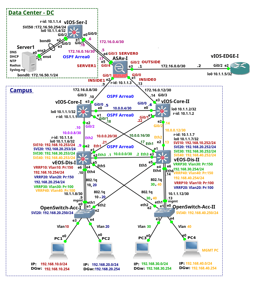
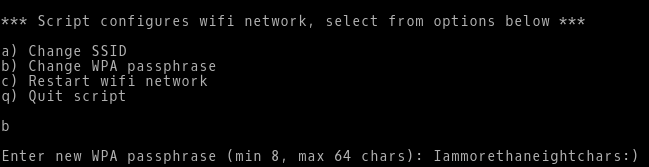
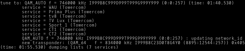
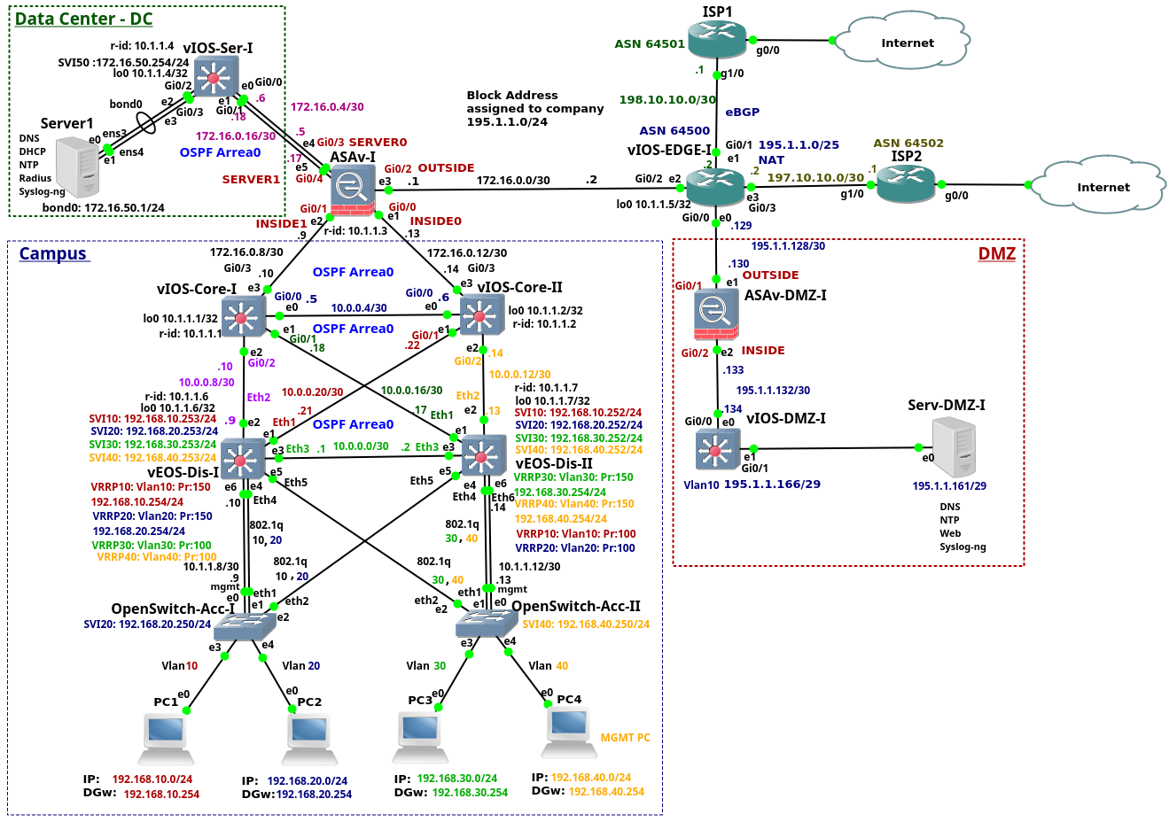
This is the fourth from the series of the articles that discuss configuration of the enterprise network. The article explains configuration of the device ASAv-I. The device is a Cisco Adaptive Security Virtual Appliance (ASAv) version 9.6(1) installed on qcow2 Qemu disk. The ASAv-I provides traffic filtering and inspection services for the campus network and Data Center (DC). It also connects the campus network and DC to the vIOS-EDGE-I edge router.

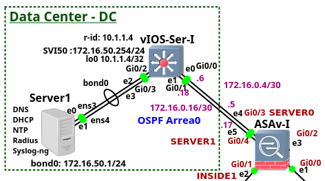
Picture 1 -  ASAv-I,  Campus, DC and  Edge Connection

Note: The recommended RAM size for ASAv instance is 2048 MB. In order to lower memory consumption,  GNS3 is configured to assign 1536 MB to the ASAv.

Note: The interface eth0 on the ASAv-I is referred as the interface Management0/0 in ASAv configuration. The interface eth0  is not connected as we use the inside interfaces for management instead. The first connected interface is then the interface eth1 that is referred as the interface GigabitEthernet0/0 in ASAv CLI. Similarly, the second connected interface eth2 is referred as the GigabitEthernet0/1 and so on.

Note: Here is the configuration file of vASA-I.

ASAv-I Configuration

Once we start ASAv, the Qemu window is launched. However we want to use GNS3 console instead of Qemu console. Therefore we need to redirect vASA output to a serial port. When ASAv boots up, copy the file coredump.cfg to a disk0 in a privileged exec mode (password is not set). Then reboot the ASAv and you should be able to manage ASAv via GNS3 console afterwards.

# copy disk0:/coredumpinfo/coredump.cfg disk0:/use_ttyS0

As a first step we configure the hostname.

ciscoasa> en
ciscoasa# conf t
ciscoasa(config)# hostname ASAv-I

1. Interfaces Configuration

The links connecting ASAv-I to the Core switches are configured with the interface name INSIDE0 and INSIDE1. They have assigned a security level 100. The links connecting ASAv-I to the DC are configured with the interface name SERVER0 and SERVER1. They have assigned a security level 50. The link connecting the ASAv-I to the  vIOS-EDGE-I router is configured with the interface name OUTSIDE and it has assigned a security level 0.

Thanks to the security levels concept, TCP and UDP traffic from the hosts connected to the inside interfaces (level 100) can reach hosts in DC, behind the server interfaces (level 50) or hosts in the Internet behind the outside interface (level 0).  The same is valid for traffic sent from DC to the Internet.  In this case, network traffic takes a path from the server interface (level 50) to the outside (level 0) interface and back.

In general, traffic initialized from the interface with a higher security level is allowed to enter the interface with a lower security level and back. However traffic initialized from the interface with a lower security level is not passed to the interface with a higher security level. For this reason traffic initialized behind the outside interface is passed neither to the inside nor to the server interfaces. If we need to allow traffic initialized from host connected to the outside interface (level 0) to enter the interfaces with a higher level (100 or 50, in our case), we have to configure an access-list (ACL). The ACL must explicitly allow particular network traffic (e.g. TCP, UDP or ICMP) to enter the outside interface.

ASAv-I(config)# interface Gi0/0
ASAv-I(config-if)# description Link to vIOS-Core-II
ASAv-I(config-if)# nameif INSIDE0
ASAv-I(config-if)# security-level 100
ASAv-I(config-if)# ip address 172.16.0.13 255.255.255.252
ASAv-I(config-if)# no shutdown
ASAv-I(config-if)# exit

ASAv-I(config)# interface Gi0/1
ASAv-I(config-if)# description Link to vIOS-Core-I
ASAv-I(config-if)# nameif INSIDE1
ASAv-I(config-if)# security-level 100
ASAv-I(config-if)# no shutdown
ASAv-I(config-if)# exit

ASAv-I(config)# interface Gi0/2
ASAv-I(config-if)# description Link to vIOS-EDGE-I
ASAv-I(config-if)# nameif OUTSIDE
ASAv-I(config-if)# security-level 0
ASAv-I(config-if)# ip address 172.16.0.1 255.255.255.252
ASAv-I(config-if)# no shutdown
ASAv-I(config-if)# exit

ASAv-I(config)# interface Gi0/3
ASAv-I(config-if)# description Link1 to vIOS-Ser-I
ASAv-I(config-if)# nameif SERVER0
ASAv-I(config-if)# security-level 50
ASAv-I(config-if)# ip address 172.16.0.5 255.255.255.252
ASAv-I(config-if)# no shutdown
ASAv-I(config-if)# exit

ASAv-I(config)# interface Gi0/4
ASAv-I(config-if)# description Link2 to vIOS-Ser-I
ASAv-I(config-if)# nameif SERVER1
ASAv-I(config-if)# security-level 50
ASAv-I(config-if)# ip address 172.16.0.17 255.255.255.252
ASAv-I(config-if)# no shutdown
ASAv-I(config-if)# exit

2. Logging Configuration

Enable Logging messages to console, RAM (buffer) and VTY session and configure appropriate logging levels.

ASAv-I(config)# logging enable
ASAv-I(config)# logging console 6
ASAv-I(config)# logging buffered 6
ASAv-I(config)# logging monitor 6

Configure syslog server server and syslog level 5 - notifications.

ASAv-I(config)# logging host SERVER0 172.16.50.1
ASAv-I(config)# logging trap notifications

Note: SERVER0 is the interface name.

Turn on monitoring logs on VTY session.

ASAv-I# terminal monitor

Note: Use command terminal no monitor to turn off displaying logs on VTY session.

Set exec timeout to 0 - you will never be disconnected from console.

ASAv-I(config)# console timeout 0

3. Default Static Route Configuration

We need to configure a default static route in order to reach hosts in the Internet. This route will be later redistributed to the OSPF process.

ASAv-I(config)# route OUTSIDE 0.0.0.0 0.0.0.0 172.16.0.2

4. Objects and Object Groups Configuration

Using objects and object groups are reusable components that help to maintain configuration. We can modify an object in one place and have it be reflected in all other places that are referencing it.

ASAv-I(config)# object network vlan10_192.168.10
ASAv-I(config-network-object)# subnet 192.168.10.0 255.255.255.0

ASAv-I(config)# object network vlan20_192.168.20
ASAv-I(config-network-object)# subnet 192.168.20.0 255.255.255.0

ASAv-I(config)# object network vlan30_192.168.30
ASAv-I(config-network-object)# subnet 192.168.30.0 255.255.255.0

ASAv-I(config)# object network vlan40_192.168.40
ASAv-I(config-network-object)# subnet 192.168.40.0 255.255.255.0

ASAv-I(config)# object network vlan50_172.16.50
ASAv-I(config-network-object)# subnet 172.16.50.0 255.255.255.0

ASAv-I(config)# object network google_dns1
ASAv-I(config-network-object)# host 8.8.8.8

ASAv-I(config)# object network google_dns2
ASAv-I(config-network-object)# host 8.8.4.4

ASAv-I(config)# object network server1
ASAv-I(config-network-object)# host 172.16.50.1

ASAv-I(config)# object network vios-l3
ASAv-I(config-network-object)# host 10.1.1.5

ASAv-I(config)# object network loopbacks
ASAv-I(config-network-object)# subnet 10.1.1.0 255.255.255.0

ASAv-I(config)# object-group network mgmt
ASAv-I(config-network-object-group)# network-object object vlan40_192.168.40

ASAv-I(config)# object-group network end_vlans
ASAv-I(config-network-object-group)# network-object object vlan10_192.168.10
ASAv-I(config-network-object-group)# network-object object vlan20_192.168.20
ASAv-I(config-network-object-group)# network-object object vlan30_192.168.30
ASAv-I(config-network-object-group)# network-object object vlan40_192.168.40

ASAv-I(config)# object-group network server_vlans_all
ASAv-I(config-network-object-group)# description All server VLANs
ASAv-I(config-network-object-group)# network-object object vlan50_172.16.50

ASAv-I(config)# object-group network google_dns
ASAv-I(config-network-object-group)# network-object object google_dns1
ASAv-I(config-network-object-group)# network-object object google_dns2

vASA-I(config)# object-group service server1_tcp_out tcp
vASA-I(config-service-object-group)# port-object eq http
vASA-I(config-service-object-group)# port-object eq https
vASA-I(config-service-object-group)# port-object eq domain

vASA-I(config)# object-group service server1_udp_out udp
vASA-I(config-service-object-group)# port-object eq ntp
vASA-I(config-service-object-group)# port-object eq domain

5. Management Protocol Configuration

5.1 ICMP ECHO Request and Echo Reply Messages on Inside Interfaces

Allow management (192.168.40.0/24), server (172.16.50.0/24) and loopback (10.1.1.0/24) subnets to ping the ASA inside interfaces.

ASAv-I(config)# icmp permit 192.168.40.0 255.255.255.0 INSIDE0
ASAv-I(config)# icmp permit 192.168.40.0 255.255.255.0 INSIDE1
ASAv-I(config)# icmp permit 172.16.50.0 255.255.255.0 SERVER0
ASAv-I(config)# icmp permit 172.16.50.0 255.255.255.0 SERVER1
ASAv-I(config)# icmp permit 10.1.1.0 255.255.255.0 INSIDE0
ASAv-I(config)# icmp permit 10.1.1.0 255.255.255.0 INSIDE1

5.2 SSH Access

ASAv-I(config)# username admin password cisco
ASAv-I(config)# aaa authentication ssh console LOCAL
ASAv-I(config)# crypto key generate rsa modulus 4096

Allow SSH access to INSIDE0 and INSIDE1 interfaces.

ASAv-I(config)# ssh 192.168.40.0 255.255.255.0 INSIDE0
ASAv-I(config)# ssh 192.168.40.0 255.255.255.0 INSIDE1

Set timeout for ssh session. Timeout is set to maximum value 60 minut.

ASAv-I(config)# ssh timeout 60

6. OSPF Protocol and Authentication Configuration

The OSPF routing protocol ensures that connectivity is between campus and DC. The static default route pointing to vIOS-EDGE-I is redistributed to OSPF process. Authentication with MD5 algorithm is used in order to prevent peering with a rouge OSPF router.

ASAv-I(config)# router ospf 1
ASAv-I(config-router)# router-id 1.1.1.3
ASAv-I(config-router)# network 172.16.0.4 255.255.255.252 area 0
ASAv-I(config-router)# network 172.16.0.8 255.255.255.252 area 0
ASAv-I(config-router)# network 172.16.0.12 255.255.255.252 area 0
ASAv-I(config-router)# network 172.16.0.16 255.255.255.252 area 0
ASAv-I(config-router)# default-information originate
ASAv-I(config-router)# exit

ASAv-I(config)# interface GigabitEthernet 0/0
ASAv-I(config-if)# ospf authentication message-digest
ASAv-I(config-if)# ospf message-digest-key 1 md5 #MyPass!034

ASAv-I(config)# interface GigabitEthernet 0/1
ASAv-I(config-if)# ospf authentication message-digest
ASAv-I(config-if)# ospf message-digest-key 1 md5 #MyPass!034

ASAv-I(config)# interface GigabitEthernet 0/3
ASAv-I(config-if)# ospf authentication message-digest
ASAv-I(config-if)# ospf message-digest-key 1 md5 #MyPass!034

ASAv-I(config)# interface GigabitEthernet 0/4
ASAv-I(config-if)# ospf authentication message-digest
ASAv-I(config-if)# ospf message-digest-key 1 md5 #MyPass!034

7. Zone Configuration

The ASAv-I  installs only one route to the subnets: 192.168.x.0/24, 10.0.0.x/30 even they are two paths to these routes available. The first path is via vIOS-Core-I (172.16.0.10) and the second path is via vIOS-Core-II (172.16.0.14). It is because ECMP is not supported across multiple interfaces, so we cannot define a route to the same destination on a different interface. However, with zones, we can have up to 8 equal cost static or dynamic routes across up to 8 interfaces within a zone. To achieve ECMP via two different interfaces, we will create a zone inside_zone and assign Gi0/0 and it Gi0/1 to this zone.

ASAv-I(config)# zone inside_zone

ASAv-I(config)# interface gigabitEthernet 0/0
ASAv-I(config-if)# zone-member inside_zone

ASAv-I(config)# interface gigabitEthernet 0/1
ASAv-I(config-if)# zone-member inside_zone

Similarly, we will create zone server_zone for Gi0/3 and Gi/04.

ASAv-I(config)# zone server_zone

ASAv-I(config)# interface gigabitEthernet 0/3
ASAv-I(config-if)# zone-member server_zone

ASAv-I(config)# interface gigabitEthernet 0/4
ASAv-I(config-if)# zone-member server_zone

Picture 2 - OSPF Routes

8. Access Lists (ACLs) Configuration

8.1 Access List out-to-ins

Permit ICMP Echo Reply packets with the source IP address 8.8.8.8 and 8.8.4.4 to end user subnets 192.168.x.0/24. The ACL allows users to check connectivity to Google public DNS with the ping command. Without the access-list, vASA does not pass ICMP Echo Reply packets from the interface outside to the interface inside or server.

ASAv-I(config)# access-list out-to-ins extended permit icmp object-group google_dns object-group end_vlans echo-reply

Permit ICMP Echo Reply packets with any source IP address to MGMT (192.168.40.0/24), Vlan50 (172.16.50.0/24) and loopback's IP 10.1.1.0/24 subnets.

ASAv-I(config)# access-list out-to-ins extended permit icmp any object-group mgmt echo-reply
ASAv-I(config)# access-list out-to-ins extended permit icmp any object loopbacks echo-reply
ASAv-I(config)# access-list out-to-ins extended permit icmp any object vlan50_172.16.50 echo-reply

Note: The other way to allow ICMP Echo Reply packets to enter the outside interface is to enable ICMP inspection on ASAv. In this case, the ASAv dynamically allows the corresponding ICMP ECHO Reply to pass through without needing to have access-list. However we do not want all devices in campus or DC to be able ping hosts in the Internet. For this reason we have shown ACL method.

Permit DNS request/reply from 8.8.8.8 and 8.8.4.4 from/to Server1 - 172.16.50.1.

ASAv-I(config)# access-list out-to-ins permit udp object-group google_dns object server1 eq 53

Permit NTP request from vIOS-L3 (10.1.1.5) to Server1.

ASAv-I(config)# access-list out-to-ins permit udp object vios-l3 object server1 eq 123

Permit syslog (UDP 514) traps from vIOS-L3 (10.1.1.5) to Server1.

ASAv-I(config)# access-list out-to-ins permit udp object vios-l3 object server1 eq 514

Apply ACL out-to-ins to the interface Outside in inbound direction.

ASAv-I(config)# interface gi0/2
ASAv-I(config-if)# access-group out-to-ins in interface OUTSIDE

8.2 Access List dc-to-ins_out

Permit hosts in subnet (172.16.50.0/24) to send traffic to any IP address, the destination TCP  port 80 (http),443 (https) and 53 (DNS).

vASA-I(config)# access-list dc-to-ins_out extended permit tcp object vlan50_172.16.50 any object-group server1_tcp_out

Permit hosts in subnet (172.16.50.0/24) to send traffic to any IP address, the destination UDP  port 123 (NTP) and 53 (DNS).

vASA-I(config)# access-list dc-to-ins_out extended permit udp object vlan50_172.16.50 any object-group server1_udp_out

Permit hosts in subnet (172.16.50.0/24) to send to ICMP Echo Request (ping)  to any IP address to the IP addresses 8.8.8.8 and 8.8.4.4.

vASA-I(config)# access-list dc-to-ins_out extended permit icmp object vlan50_172.16.50 object-group google_dns echo

Permit hosts in mgmt VLAN40 (192.168.40.0/24) to ping Server1.

vASA-I(config)# access-list dc-to-ins_out extended permit icmp object vlan50_172.16.50 object vlan40_192.168.40 echo-reply

Apply ACL dc-to-ins to the interfaces SERVER0 and SERVER1 in inbound direction.

vASA-I(config)# access-group dc-to-ins_out in interface SERVER0
vASA-I(config)# access-group dc-to-ins_out in interface SERVER1

Picture 3 - Access-Lists

9. NTP Configuration

ASAv-I(config)# ntp server 172.16.50.1
ASAv-I(config)# clock timezone UTC+2 +2

Picture 4 - Checking NTP Associations

10. Radius Server Configuration

10.1 Create Local User

Create a local user with full access in case Radius servers is not reachable.

ASAv-I(config)# username admin password cisco privilege 15

We also set password for privileged exec mode.

ASAv-I(config)# enable password cisco

Now Activate AAA.

vIOS-Core-I(config)# aaa new-model

10.2 Radius Server

The RADIUS server and a vASA use a shared secret text string to encrypt passwords and exchange responses.To configure RADIUS to use the AAA security commands, we must specify the host running the RADIUS server daemon and a secret text (key) string that it shares with the ASAv.

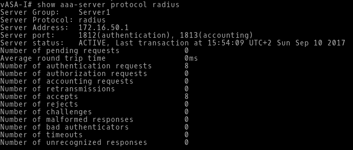
ASAv-I(config)# aaa-server Server1 protocol radius
ASAv-I(config-aaa-server-group)# exit

ASAv-I(config)# aaa-server Server1 (SERVER0) host 172.16.50.1 test123
ASAv-I(config-aaa-server-host)# key test123
ASAv-I(config-aaa-server-host)# authentication-port 1812
ASAv-I(config-aaa-server-host)# accounting-port 1813

10.3 Authentication for Access to Serial Console

If all servers in the server group have been deactivated, authentication will be done against the local database.

ASAv-I(config)# aaa authentication serial console Server1 LOCAL

10.4 Authentication for Access via SSH

ASAv-I(config)# aaa authentication ssh console Server1 LOCAL

10.5 Authentication for Access to Privileged Exec Mode (Enable)

ASAv-I(config)# aaa authentication enable console Server1 LOCAL

Transition a failed AAA server to Active.

ASAv-I(config)# aaa-server Server1 active host 172.16.50.1

Picture 5 - Checking AAA Server

11. Application Inspection Configuration

We also need to inspect network traffic on application layer to check both Layer 7 header and the payload of the segments to ensure that packets do not carry harmful content. To add http inspection to the list of default inspected applications, we will create an optional policy-map type http named http_map.  In case of http protocol violation, TCP traffic is dropped.

ASAv-I(config)# policy-map type inspect http http_map
ASAv-I(config-pmap)# parameters
ASAv-I(config-pmap-p)# protocol-violation action drop-connection log

Note: class-maps identify traffic, actions are assigned with policies (policy-map), and then the service policies are activated on interfaces (service-policy).

Assign our http_map policy to the global_policy map.

ASAv-I(config)# policy-map global_policy
ASAv-I(config-pmap)# class inspection_default
ASAv-I(config-pmap-c)# inspect http http_map

ASAv-I(config)# service-policy global_policy global

Check inspected protocols in running-config.

Picture 6 - Checking Inspected Application Protocols

To show statistic of service-policy inspect for a particular application protocol, use the command below. The command shows statistic for DNS protocol.

Picture 7 - DNS Inspection Statistics

Linux PiCore on Raspberry Pi - First Steps

$
0
0

The blog post contains notes about the installation of piCore Linux on Raspberry Pi 3 computer. The related topic is well known, discussed by many similar posts however the article represents my own copy & paste reference for later usage.

The first generation of Raspberry Pi 1 has been with us since February 2012. Recently in version 3B, the Pi3 is equipped with 1.2 GHz 64-bit quad-core ARM Cortex-A53 processor, 1 GB of RAM and it has integrated 2.4 GHz WiFi 802.11n (150 Mbit/s), Bluetooth 4.1 (24 Mbit/s) on Broadcom BCM43438 chip. It also provides the integrated 10/100 Ethernet port. These factors along with the cheap price (~ 35 US), small size (~ 85.60mm x 56mm x 21mm), low weight (~ 45g) and low power consumption (maximum 1.34 A or 6.7 W under stress when peripherals and WiFi are connected) makes this single-board computer ideal candidate for use in the recent Internet of Things (IoT) world.

Raspberry Pi can run several OSs built for ARM architecture such as Windows 10 IoT Core, Raspbian (based on Debian), Ubuntu Mate and many others. The Linux distributions offer either full desktop environment or they are released as lite distributions, without GUI.  Personally, I use piCore Linux that is the lightweight ARM clone of Tinycore Linux. The Core Linux is unique because it runs entirely in RAM. It  touches the SD card only when some action is needed, for instance a new extension is being installed. It helps to extend of the lifetime of SD card which is a flash memory with limited write cycles (~ 100,000).

I do believe that the RAM size 1024MB included in Pi 2 and 3 models is capable to accommodate all installed piCore extensions for a typical IoT device. You can just boot piCore from SD card and remove the card afterwards. In this scenario, the system cannot be destroyed by hackers or they cannot install backdoors in to device as there is not storage medium inserted in the device. However either electricity must be secured to avoid of piCore reboot or the SD card must be presented in case of reboot. On the other side,  digital evidences might by destroyed easily just switching off the Raspberry box.

The steps below discuss deployment Linux piCore on SD card.

1. Downloading piCore for Raspberry Pi3 and Copy Image to SD Card

We will download the latest piCore 9.0.3 and save it to  x86-64 Ubuntu

$ wget http://distro.ibiblio.org/tinycorelinux/9.x/armv7/releases/RPi/piCore-9.0.3.zip

$ unzip RPi/piCore-9.0.3.zip

Be sure that SD card is not mounted. If yes, umount the card.

$ sudo umount /dev/mmcblk0

Copy the extracted piCore image to SD card.

$ sudo dd bs=4M if=piCore-9.0.3.img of=/dev/mmcblk0 status=progress conv=fsync

Remove SD card from Ubuntu and insert it to Raspberry Pi.

2. SD Card Partitioning

We will done SD partitioning on piCore Linux. This process ensures that all capacity of SD card will be used for the second partition.

$ sudo fdisk -u /dev/mmcblk0

List the available partitions. Press 'p'

Picture 1 - SD Card Before Resizing Partition mmcblk0p2

Device /dev/mmcblk0p2 is a Linux ext4 partition which contains preinstalled extensions, openssh and mc (Midnight Commander) and configuration files. It is a small partition with no free space so we must expand its size to have enough room for additional extensions, updates and backups.

Starting sector for the partition /dev/mmcblk0p2 is 77824 and ending sector is 100351. The size of the second partition is 11 MB. To delete the second partition press 'd' and type '2'. Write changes with 'w'. Afterwards run fdisk again.

$ sudo fdisk -u /dev/mmcblk0

  • Create a new partition with 'n'
  • Press 'p' for primary and '2' for the second partition
  • Enter the first sector - 77824
  • Press Enter for the default end sector
  • Save changes with 'w'

Now insert SD to Raspberry Pi and expand a file system to the new partition boundaries typing the command below as root:

$ sudo resize2fs /dev/mmcblk0p2

Note: the default user is tc with the password piCore.

Picture 2 - SD Card After Resizing Partition mmcblk0p2

As you can see, the size of the partition /dev/mmcblk0p2 has been extended to 3.7 GB. It corresponds with the overall capacity 4 GB of SD card. Now, shutdown piCore, remove SD card and make copy of the card with dd command on Ubuntu.

$ sudo dd bs=4M if=/dev/mmcblk0 of=piCore-9.0.3-clean.img status=progress conv=fsync

Our piCore is ready for installation additional extensions. They will be stored on the partition mmcblk0p2.

Raspberry Pi3 WIFI Router Based on Linux piCore

$
0
0

Recently I have bought a Christmas present for myself from GearBest, costing only $49,21 USD. It includes Raspberry Pi 3 single board computer along with 2.5A power supply, case and several heat sinks. Pi3 is the latest and the most powerful Raspberry model, equipped with 1.2GZ 64-bit ARM processor, 1GB RAM and integrated 10/100 Ethernet port and Wifi 802.11n. Although I can simply use it as a cheap desktop computer, I have different goal in my mind.

Six years ago, I built my own SOHO router/switch base on Intel Pentium III - 733Mhz. It was working great but to save electricity consumption I have never used it in production. However, I have never completely given up idea to build and use my own  router. It comes true thanks to Raspberry Pi3 computer as it consumes maximum 1.34 A or 6.7 W under stress when peripherals and WiFi are connected.

Picture1 - Raspberry Pi 3 Model B
Source: http://fosssig.com/tinkerers/1-raspberry-pi-and-kodi/

To shorten the story, I have built a wifi router that runs piCore 9.0.3 on Raspberry PI3. The clients are connected via wireless network to the router that runs hostapd. The hostapd is configured for WPA2 authentication and AES encryption. The router is running DHCP server on the interface wlan0 (IP address 192.168.230.1), providing IP addresses for wireless clients from the subnet 192.168.230.0/24 along with IP address of the default gateway 192.168.230.1.

DHCP also assigns IP address of DNS sever - 192.168.230.1. Both DNS and DHCP are implemented by dnsmasq extension. Router's eth0 interface is connected to ISP network and it gets the IP address from ISP's DHCP server. I have built ppp extension so the router can also connect to ISP using PPPoE protocol. In case the advanced routing is neeeded (OSPF, BGP, etc), FRrouting extension is also available. Of course, to connect WLAN network to the public Internet, NAT is done either on eth0 or ppp0 interfaces. It is implemented by extension iptables using NAT table.

Picture 2 - Raspberry PI Router Connected in Home Network

Thanks to its small size, the router can be used as portable secure wifi router sharing Ethernet connection with other devices inside your room. Moreover, you can load the router with TOR client or any other extensions if needed. Before you leave the room, you can easily destroyed any digital evidence removing the SD card from the router. PiCore will keep working as it runs entirely in RAM. In case you don't need router anymore, you just write another image to SD card and boot your Raspberry from this image.

Note: Although the IPv6 module is loaded in piCore kernel, IPv6 protocol is not tested. For this reason, consider the router as IPv4 based only.

1. Image and Configuration Files

Download the zip file, extract the image and copy it to your SD card with dd command. The router image is a copy of the 4GB SD card thus the card with the equal capacity or bigger is needed. Read this guide for reference.

Core-9.0.3-router0.1.zip [2,2 GB]
Core-9.0.3-router0.1.img.md5.txt [61B]

Although the router is fully operational, I have also attached the configuration guide and files for reference below.

PiCore OS configuration files:
/opt/.filetool.lst [556B]
/opt/bootsync.sh [492B]
/opt/bootlocal.sh [995B]

The router is loaded with the following extensions.

2. After Install Tasks

Although router is operational once the image is copied to SD card, we should do some basic after install steps. They include changing the default SSID and wpa_passphrase, setting new password  for user tc and configuring and hardening network connection to ISP. For this purpose I prepared the after initial scripts that you can run after the first boot. The scripts are located in the directory /home/tc/.

2.1 Changing password for user tc

The default password for user tc is piCore. I strongly recommend to change it immediately.

$ sudo /home/tc/passwdconf.sh

Picture 3 - Changing Password for User 'tc'

2.2 Configuring connection to ISP

By default, the router is working as a typical wifi router with IP address assigned from ISP on its Ethernet port. However, if PPPoE is required to establish connection to ISP, additional configuration is needed. It includes enabling pppd daemon, changing default credentials and NAT reconfiguration. Luckily, the script pppoeconf.sh takes care of this job. In order to connect to ISP using PPPoE and CHAP protocol, issue the command below.

$ sudo /home/tc/pppoeconf.sh

Picture 4 - Changing Credentials for PPPoE Connection and Enabling pppd Daemon

Note: To avoid routing issues after PPPoE configuration, it's recommended to reboot your router.

2.3 Wireless network configuration

Although, the wireless network is operational once the router is booted, the WLAN is using the default SSID piCore and WPA passphrase raspberry.  Use the script wificonf.sh to changed them.

$ sudo /home/tc/pppoeconf.sh

Picture 5 - Changing WPA Passphrase for WLAN

Below are shown the network interfaces for reference.

Picture 6 - List of Network Interfaces

2.4 Enabling Firewall

We need to prevent attackers from the Internet to connect to the router.  Below is the list of open TCP ports that were found by nmap from the PC located in the Internet, before enabling firewall.

Picture 7 - Opened TCP Ports

The script iptablesconf.sh configures iptables to allow only established connection on Ethernet port. Connection from the Internet to the router that is not initialized from WLAN network is dropped. The script  also allows input traffic from WLAN network to reach the router's interfaces.

Picture 8 - Enabling Firewall

3. Testing

In case you need to know more about the speed of the integrated Ethernet port and Wifi check this article.  My findings are that download speed (28.7Mbps) achieved by  Raspberry piCore router is worse than the speed of Belkin router (33.5 Mbps). 

Picture 9 - Network Statistics  Achieved by Raspberry Pi3 piCore Router

However,  jitter 1ms achieved by Raspberry is significantly less that jitter 62ms, measured when Belkin router is used. My user experience also also confirms this finding .


Picture 10 - Network Statistics Achieved by Belkin Router

The high jitter value might be caused by interference of Wifi signal from other nearby WLANs or it might indicate problem with Belkin router itself.


Digital DVB-T on Raspbian

$
0
0

Recently, I have been asked to get working Digital Video Broadcasting - Terrestria (DVB-T) tunner on Raspberry PI 3. The tunner is Cinergy DVB-T stick from Terratec. Below are my notes describing installation of the stick on Raspbian Linux 9.1 Stretch. I hope someone find them useful.

1. Copy Raspbian to SD CARD (on Ubuntu)

First, we need to copy Raspbian installation image to SD card. Below is the example using dd command on Linux.

$ sudo dd bs=4M if=2017-09-07-raspbian-stretch.img of=/dev/mmcblk0 status=progress conv=fsync

Insert SD card to Raspberry and power on the box. The default user is pi with the password raspberry. Enable SSH and VNC server for remote box administration. Navigate to Menu-> Preferences-> Raspberry PI Configuration.

2. Install Firmware

Inspect kernel for any error message connected with DVB-T tunner.

$ dmesg

Picture 1 - Missing firmware isdbt_rio.imp

Download firmware file isdbt_rio.imp (md5 - 9b762c1808fd8da81bbec3e24ddb04a3) from here. I have also uploaded it to Google disk. You can download and copy the file to the directory /lib/firmware with the command below.

$ sudo wget https://drive.google.com/uc?id=1MwDGSG4ZEm3eeJuf0gS686Be-ngx4rKR -O /lib/firmware/isdbt_rio.inp

Reboot PI and check kernel for any other kernel error messages.

Picture 2 - Missing firmware dvb_rio.imp

Download firmware file dvb_rio.imp (md5 - 146156b55ce6fc586470f28194add5a7) from here. or from Google disk. Alternatively, you can download and copy firmware to /lib/firmware with the command below.

$ sudo wget https://drive.google.com/uc?id=1IxpPmGiYEM7uHPs8ne3QIfxJHJiTYsN- -O /lib/firmware/dvb_rio.imp2

In order to get DVB-T tuner working, we need to set a default mode to 4 for the module smsmdtv. Without this setting, we get message no usable  terrestrial card found.

Picture 3 - Terrestrial Card not found 

$ echo "options smsmdtv default_mode=4" | sudo tee /etc/modprobe.d/smsmdtv.conf

Afterwards, we can reboot Raspbian again.

2. Channel Tunning

We install a command-line scanning tool for DVB channels on Raspbian and we will try to search for transponders.

$ sudo apt-get install w-scan

Now, we can scan the channels.

$ w_scan -ft  -x

-ft  -> terrestrian [default]
-x -> generate initial tuning data for (dvb-) scan

Picture 4 - Searching for Channels

Now, we can install DVB-T player me-tv with the command below. The navigate to Menu -> Sound & Video -> Me TV.

$ sudo apt-get install me-tv

The very first time the player is started, the wizard is opened. Click option AutoScan and select your country. Then click Next button.

Picture 5 -Selecting Auto scan Option

The player will search channels for you.

Picture 6 -Searching for Channels

When searching is finished, just click Add button and then OK.

Picture 7 - Adding Channels

Once channels are added, you can start watching TV.

Picture 8 - Watching TV

Here is the output from lsmod command in case, it is needed for troubleshooting.

Enterprise Network on GNS3 - Part 5 - Data Center

$
0
0

The article is the fifth of the series of the articles discussing the enterprise network configuration. The article focus on the Data Center (DC) configuration. DC consists of the two devices - Server1 and the switch vIOS-Ser-I. Of course, the DC network with a single switch and the server is far away from any known DC network design. Typically, modern horizontally scaled large-size Layer 3 DCs consist of thousands of servers connected to the Top of Rack (ToR) l3 switches and they follow leaf and spine design. The DC of this size can be hardly emulated on a single PC. For this reason I only share the configuration of the Cisco L3 switch that is located in our DC. The switch is running Cisco vIOS-L2, version 15.2 and it has assigned 768MB RAM by GNS3.

The switch vIOS-Ser-I connects Ubuntu Linux Server to DC network. The configuration of the services such as bonding, NTP, DHCP, Syslog-ng, DNS and RADIUS running on the server is explained in more details later.

Picture 1 - Data Center

Note: The configuration file of the device vIOS-Serv-I is attached here.

1. Switch vIOS-Ser-I Configuration

Rather than explaining every line of the configuration, we will discuss how is the vIOS-Serv-I connected into the other devices. The switch is connected with point-to-point layer3 links to the Cisco ASAv-I. The OSPF routing protocol with Message digest (MD5) authentication password is configured on the switch.

Picture 2 - List of Interfaces

The switchports Gi0/2 and Gi0/3 connect the switch to the Server1 and they are configured as the access ports in VLAN50. The links are bonded together as a single etherchannel port (L2 port-channel) using the command channel-group 1 mode on. Traffic is loaded based on source XOR destination MAC address across the links.

Picture 3 - Etherchannel Summary

The switch is acting as default gateway with the IP address 172.16.50.254/24 configured on the interface SVI50. This IP address is configured on the Server1 under IPv4 configuration.

The switch is synchronizes its time with the Server1 using NTP. It is also configured to send traps with the severity 5 - notification and lower (1- alerts, 7 - debugging) to syslog-ng daemon running on the Server1. The access to the console and vty lines is authenticated against RADIUS server running on the Server1.

Picture 4 - RADIUS Authentication Checking

2. Server1 Configuration

2.1 After Installation Steps

The Server1 is running Ubuntu 16.04.3 LTS Xenial. Once Ubuntu is installed, we will fetch the list of available updates and upgrade the current packages with the commands below.

Picture 5 - Ubuntu Linux Version

$ sudo su
# apt-get update && apt-get upgrade

I prefer Vim editor to the default installed Nano editor. We can install Vim with the command.

# apt-get install vim

Change the hostname and add a pair hostname and an IP address 127.0.0.1 into the file /etc/hosts.

# vi /etc/hostname
Server1

# echo "127.0.1.1 Server1" >> /etc/hosts

After reboot, the hostname is changed to Server1. Now configure Ubuntu to display a security banner for SSH connections.

# vi /etc/issue.net

Welcome to Server1
All connections are monitored and recorded
Disconnect IMMEDIATELY if you are not an authorized user!

Edit a configuration file of OpenSSH sever. Uncomment a line starting with a keyword #Banner.

# vi /etc/ssh/sshd_config
Banner /etc/issue.net

Restart SSH service.

systemctl restart ssh

2.2. Redirecting VGA Output to Serial Port

Server1 appliance is running inside GNS3 topology. GNS3 supports a serial console for connection to a serial port of an appliance. To use a console for Server1, we are going to reconfigure Ubuntu to redirect VGA output to a serial port. Afterwards we can easily connect to his serial port with a right click on the appliance and select Console from the list. Below is a minimal configuration of Ubuntu for redirection of VGA to the serial port.

$ sudo su
# vi /lib/systemd/system/ttyS0.service

[Unit]
Description=Serial Console Service

[Service]
ExecStart=/sbin/getty -L 115200 ttyS0 vt102
Restart=always

[Install]
WantedBy=multi-user.target

Now reload systemd manager configuration and enable ttyS0 service. Then start ttyS0 service.

# systemctl daemon-reload
# systemctl enable ttyS0
# systemctl start ttyS0

Reboot the Server1 and connect to its serial port with GNS3.

2.3 Interfaces and Bonding Configuration

First, we need to load a bonding module to Linux kernel.

$ sudo su
# modprobe bonding

Check if the module is loaded into the kernel.

# lsmod | grep bond
bonding 139264 0

Configure the kernel to load the bonding module after reboot.

# echo "bonding" >> /etc/modules

Check available interfaces with the ifconfig -a command. They are three Ethernet interfaces presented - bond0, ens3 and ens4. Let's add interfaces ens3 and ens4 to bond0 interface and configure IP address on the bond0. Edit the configuration file  /etc/network/interfaces as it is shown here. Afterwards check status of bonding with the command below.

Picture 6 - Checking Bonding Status

The bonding mode is set to 0 - load balancing and round robin. This is default mode that provides load balancing and fault tolerance.

2.4 Forwarding DNS Server Using Bind

Forwarding Domain Name System (DNS) server forwards DNS requests to an outside resolving server and then caches the results to use for later queries. We install and configure Bind that will forward DNS queries to se Google public DNS servers.

Note: The configuration file /etc/bind/named.conf.options is here.

2.4.1 Install Bind Server Packages

$ sudo apt-get update
# sudo apt-get install bind9 bind9-doc

2.4.2 Bind Configuration

a) Define Access-List For Clients

Create an access-list which identifies the clients allowed to access DNS server. The access-list should list all the clients' IP subnets.  First, modify the Bind configuration file below. All the following configuration changes will be done inside this file. Put the lines below above the line beginning with the options block.

# vi /etc/bind/named.conf.options

acl ourclients {
10.0.0.0/24;
10.1.1.0/24;
192.168.10.0/24;
192.168.20.0/24;
192.168.30.0/24;
192.168.30.0/24;
172.16.0.0/24;
172.16.50.0/24;
localhost;
localnets;
};

b) Allow Recursion and Query

Allow recursion and configure a parameter allow-query referring to the access-list for our clients. But the lines bellow inside the option block.

recursion yes;
allow-query {
ourclients;
};

c) Configure Forwarders

We need to provide Google public recursive name servers IP addresses 8.8.8.8 and 8.8.4.4. Change the forwarders block as following.

forwarders {
8.8.8.8;
8.8.4.4;
};

To configure recursive name servers, add the following line below into the forwarders block. DNS server will forward request to Google DNS public servers instead of trying to resolve queries by itself.

forward only;

d) Enable DNSsec

Enable DNSsec. Change the line dnssec-validation no to dnssec-validation yes and add the line dnssec-enable yes.

dnssec-enable yes;
dnssec-validation yes;

Check the configuration file for errors with the command below. If there is not an error, the output is blank.

# named-checkconf

Alternatively, inspect /var/log/syslog for errors.

e) Logging Queries

Create a directory /var/log/named  that stores Bind log messages and change owner and group to bind.

# mkdir /var/log/named/
# chown bind:bind /var/log/named/

Add the following commands at the end of /etc/bind/named.conf.options

logging {
channel query_log {
  file "/var/log/named/bind.log" versions 3 size 5m;
  severity info;
  print-time yes;
  print-severity yes;
  print-category yes;
};
category queries {
  query_log;
};
};

Then add the line querylog yes to the option block.

querylog yes;

Check configuration again with the command below and restart Bind.

# named-checkconf
# systemctl restart bind9

The log file /var/log/named/bind.log should now contain DNS queries.

Picture 7 - Logging DNS Queries

2.5 Network Time Protocol Server Installation and Configuration

NTP server provides precise time for the hosts and network devices. It is running on Server1. Here is the configuration file /etc/ntp.conf.

2.5.1 Install NTP Daemon and Utilities Package

$ sudo apt-get install ntp

2.5.2 NTP Client Configuration

$ sudo su
# vi /etc/ntp.conf

a) Specify NTP Public Servers

Comment out the the following lines and specify NTP servers near to you. These are the default pre-configured public NTP servers.

#pool 0.ubuntu.pool.ntp.org iburst
#pool 1.ubuntu.pool.ntp.org iburst
#pool 2.ubuntu.pool.ntp.org iburst
#pool 3.ubuntu.pool.ntp.org iburst

#pool ntp.ubuntu.com

# Add the following lines.

server 0.sk.pool.ntp.org
server 1.europe.pool.ntp.org
server 3.europe.pool.ntp.org

b) Restrict Access of Public NTP Servers to our NTP Server

restrict -4 default kod nomodify notrap nopeer noquery
restrict -6 default kod nomodify notrap nopeer noquery

Time will be synchronized with public NTP server but the servers are not allowed to modify the run-time configuration or query our Linux NTP server.

c) Allow Our Hots to Query Time With Our NTP server

Add the following lines.

restrict 10.1.1.0 mask 255.255.255.0 nomodify notrap
restrict 172.16.0.0 mask 255.255.255.0 nomodify notrap
restrict 10.0.0.0 mask 255.0.0.0 nomodify notrap
restrict 192.168.0.0 mask 255.255.0.0 nomodify notrap

Restart NTP service and check status of time synchronization.

# systemctl restart ntp

Use the  ntpq utility to monitor NTP daemon ntpd operations.

root@Server1:/home/ubuntu# ntpq -p

Picture 8 - Monitoring NTP Daemon Operations With NTP Query Utility

The actual time can be checked with the date command.

root@Server1:/home/ubuntu# date
Thu Apr 6 11:04:42 CEST 2017

2.6 DHCP Server Installation and Configuration

We need to run DHCP server on Server1 as we want hosts in the end-user networks (192.168.10-30.x/24 ) and the network 172.16.50.0/24 to obtain their IP addresses automatically. In order to get this configuration working the command ip helper-address 172.16.50.1 must be configured under SVI 10, 20 and 30 configuration. We have already done it in Part3.

Install ISC DHCP server for automatic IP address assignment for clients on the subnets 192.168.x.0/24 and 172.16.50.0/24.

$ sudo apt-get install isc-dhcp-server

Add the lines below into DHCP configuration file /etc/dhcp/dhcpd.conf.  The configuration file is here.

# vi /etc/dhcp/dhcpd.conf

option domain-name "mycompany.sk";

default-lease-time 600;
max-lease-time 7200;

subnet 172.16.50.0 netmask 255.255.255.0 {
range 172.16.50.1 172.16.50.1;
option routers 172.16.50.254;
option subnet-mask 255.255.255.0;
option broadcast-address 172.16.50.255;
option domain-name-servers 172.16.50.1;
option ntp-servers 172.16.50.1;
}
subnet 192.168.10.0 netmask 255.255.255.0 {
range 192.168.10.1 192.168.10.240;
option routers 192.168.10.254;
option subnet-mask 255.255.255.0;
option broadcast-address 192.168.10.255;
option domain-name-servers 172.16.50.1;
option ntp-servers 172.16.50.1;
}

subnet 192.168.20.0 netmask 255.255.255.0 {
range 192.168.20.1 192.168.20.240;
option routers 192.168.20.254;
option subnet-mask 255.255.255.0;
option broadcast-address 192.168.20.255;
option domain-name-servers 172.16.50.1;
option ntp-servers 172.16.50.1;
}

subnet 192.168.30.0 netmask 255.255.255.0 {
range 192.168.30.1 192.168.30.240;
option routers 192.168.30.254;
option subnet-mask 255.255.255.0;
option broadcast-address 192.168.30.255;
option domain-name-servers 172.16.50.1;
option ntp-servers 172.16.50.1;
}

Now we need to specify the interface, DHCP should listen to. Add the interface  bond0 to the file /etc/default/isc-dhcp-server. Also check if the path to DHCP configuration file /etc/dhcp/dhcpd.conf is correct.

# vi /etc/default/isc-dhcp-server

DHCPD_CONF=/etc/dhcp/dhcpd.conf

INTERFACES="bond0"

Now we can enable and start DHCP service. Leased IP addresses are stored in the file /var/lib/dhcp/dhcpd.leases.

# sudo systemctl enable isc-dhcp-server
# sudo systemctl start isc-dhcp-server

2.7 FreeRADIUS Installation and Configuration

If we want to have the login access to the network devices authenticated in centralized manner, FreeRadius is a need. It is cost-free and highly effective solution.

2.7.1 Install and Configure Freeradius

$ sudo apt-get install freeradius

Add the list of the clients into FreeRADIUS configuration with the same shared key test123. Below is the example for  ASAv-I and vIOS-Core-I devices.

# vi /etc/freeradius/clients.conf

client 172.16.0.5/32 {
secret = test123
shortname = ASAv-I
nastype = cisco
}

client 172.16.0.17/32 {
secret = test123
shortname = ASAv-I
nastype = cisco
}

client 10.1.1.1/32 {
secret = test123
shortname = vIOS-Core-I
nastype = cisco
}

Add following lines to the users configuration file as it is shown below. The configuration file is here.

# vi /etc/freeradius/users

# User privilege level 1
raadmin Cleartext-Password := "racisco"
Service-Type = NAS-Prompt-User,

# User privilege level 15
raadmin15 Cleartext-Password := "racisco15"
Service-Type = NAS-Prompt-User,
cisco-avpair = "shell:priv-lvl=15"

# Enable password
$enab15$ Cleartext-Password := "racisco"
Service-Type = NAS-Prompt-User,

To log authentication requests, change the lines below from no to yes in the file /etc/freeradius/radiusd.conf. By default, logs are stored in the file /var/log/freeradius/radius.log.

# vi /etc/freeradius/radiusd.conf

auth = yes

auth_badpass = yes
auth_goodpass = yes

Restart FreeRadius service.

# systemctl restart freeradius

Picture 9 - Logged Authentication Requests

Note: If you want to check debug messages, stop freeradius service and start it with parameter -X (full debugging).

# freeradius -X

2.8. Syslog-ng Installation and Configuration

We want each device to send logs to one central location. For this purpose, we will install syslog-ng on Server1. The logs are stored inside the directory tree /var/log/syslog-ng/IP/year/month/day where IP is the IP address of a particular device.

$ sudo apt-get install syslog-ng
$ sudo su

Configure Syslog-ng. Here is the configuration file /etc/syslog-ng/conf.d/firewalls.conf.

# cd /etc/syslog-ng/conf.d

# vi firewalls.conf

options {
create_dirs(yes);
owner(ubuntu);
group(ubuntu);
perm(0640);
dir_owner(ubuntu);
dir_group(ubuntu);
dir_perm(0750);
};

source s_net {
tcp(ip(0.0.0.0) port(514));
udp(ip(0.0.0.0) port(514));
};

destination d_host-specific {
file("/var/log/firewalls/$HOST/$YEAR/$MONTH/$HOST-$YEAR-$MONTH-$DAY.log");
};

log {
source(s_net);
destination(d_host-specific);
};

# service syslog-ng restart

Picture 10 - Received Logs from Devices Stored In Directories

Enterprise Network on GNS3 - Part 6 - Edge Router and ISPs

$
0
0

This is the sixth article from the series of the articles discussing the configuration of an entire enterprise network. The article explains the configuration of the edge router vIOS-EDGE-I and configuration of ISP routers.  Now let's say few words about the router vIOS-EDGE-I. The router is Cisco IOSv Qemu appliance, version 15.6(2)T. It has assigned 512MB RAM by GNS3. The router connects all three parts of the company network to the Internet. These parts are the the campus network, data center and DMZ.

Picture 1 - Company Connection to the Internet via vIOS-EDGE-I

The company has assigned the prefix 195.1.1.0/24. Devices located in DMZ have assigned the prefix 195.1.1.128/25. The prefix 195.1.1.0/25 is assigned for devices hidden behind NAT. NAT is configured on vIOS-EDGE-I router, translating campus and data center subnets to the subnet 195.1.1.128/25. The router is connected to the upstream providers via their Ethernet ports Gi0/1 and Gi0/3. This is a single multi homed topology when a company is connected to two upstream providers with a single edge router. The entire prefix 195.1.1.0/24 is advertised to the both ISPs via BGP routing protocol. When one of the ISP goes down, the incoming traffic to the prefix 195.1.1.0/24 is not no affected. The outgoing traffic from the edge router to the Internet is primary sent to ISP1. If the ISP1 goes down, traffic is sent via ISP2.

Routers ISP1 and ISP2 are Cisco 7206 routers, emulated by Dynamips. They are running IOS version 15.2(4)S4 and they have assigned 512MB RAM by GNS3. Both routers are bridged to the interface enp4s0f2 by GNS3 cloud via their interfaces Gi0/0. The interface enps4s0f2 is NIC presented in my laptop. The NIC is connected to the SOHO router that connects home network to the Internet. The routers ISP1 and IPS2 receive the IP addresses on the ports GigabitEthernet0/0 ports from DHCP server running on SOHO router. DHCP server configured on SOHO router assigns IP address in a range 172.17.100.2/16 - 172.17.100.100/16 along with the IP address of the default gw 172.17.100.1.

Picture 2 - ISP1 Connection to SOHO Network Using GNS3 Cloud

Note: The configuration files are: vIOS-EDGE-I, ISP1 and ISP2.

1. Router vIOS-EDGE-I Configuration

Firstly, we change the hostname of the edge router.

Router> en
Router# conf t
Router(config)# hostname vIOS-EDGE-I

1.1 Create Local User and Set password to Privileged Exec Mode

Create a local user.  We do not want to authenticate users accessing Edge Router using RADIUS.

vIOS-EDGE-I(config)# username admin secret cisco

We will also set password for privileged exec mode.

vIOS-EDGE-I(config)# enable secret cisco

1.2 IP Addresses Configuration

vIOS-EDGE-I(config)# interface GigabitEthernet 0/0
vIOS-EDGE-I(config-if)# description Link to ASA-DMZ-I
vIOS-EDGE-I(config-if)# ip address 195.1.1.129 255.255.255.252
vIOS-EDGE-I(config-if)# no shutdown

vIOS-EDGE-I(config)# interface GigabitEthernet 0/2
vIOS-EDGE-I(config-if)# description Link to ASAv-I
vIOS-EDGE-I(config-if)# ip address 172.16.0.2 255.255.255.252
vIOS-EDGE-I(config-if)# no shutdown
vIOS-EDGE-I(config-if)# exit

vIOS-EDGE-I(config)# interface GigabitEthernet 0/1
vIOS-EDGE-I(config-if)# description Link to ISP1
vIOS-EDGE-I(config-if)# ip address 198.10.10.2 255.255.255.252
vIOS-EDGE-I(config-if)# no shutdown
vIOS-EDGE-I(config-if)# exit

vIOS-EDGE-I(config)# interface GigabitEthernet 0/3
vIOS-EDGE-I(config-if)# description Link to ISP2
vIOS-EDGE-I(config-if)# ip address 197.10.10.2 255.255.255.252
vIOS-EDGE-I(config-if)# no shutdown
vIOS-EDGE-I(config-if)# exit

vIOS-EDGE-I(config)# interface loopback 0
vIOS-EDGE-I(config-if)# description Management
vIOS-EDGE-I(config-if)# ip address 10.1.1.5 255.255.255.255
vIOS-EDGE-I(config-if)# no shutdown
vIOS-EDGE-I(config-if)# exit

1.3 Network Address Translation - NAT Configuration

Configure Port Address Translation (PAT) to translate all campus subnets network and a data center subnet into public IP address pool 195.1.1.0/25.

Standard access-list 1 selects subnets that are going to be translated.

vIOS-EDGE-I(config)# access-list 1 permit 192.168.10.0 0.0.0.255
vIOS-EDGE-I(config)# access-list 1 permit 192.168.20.0 0.0.0.255
vIOS-EDGE-I(config)# access-list 1 permit 192.168.30.0 0.0.0.255
vIOS-EDGE-I(config)# access-list 1 permit 192.168.40.0 0.0.0.255
vIOS-EDGE-I(config)# access-list 1 permit 10.0.0.0 0.0.0.255
vIOS-EDGE-I(config)# access-list 1 permit 10.1.1.0 0.0.0.255
vIOS-EDGE-I(config)# access-list 1 permit 172.16.0.0 0.0.0.255
vIOS-EDGE-I(config)# access-list 1 permit 172.16.50.0 0.0.0.255
vIOS-EDGE-I(config)# access-list 1 deny any

Define NAT pool of inside global addresses.

vIOS-EDGE-I(config)# ip nat pool 1 195.1.1.1 195.1.1.127 netmask 255.255.255.128

Configure NAT Overload (Port Address Translation).

vIOS-EDGE-I(config)# ip nat inside source list 1 pool 1 overload

Define inside and outside interfaces.

vIOS-EDGE-I(config)# interface GigabitEthernet 0/0
vIOS-EDGE-I(config-if)# ip nat outside

vIOS-EDGE-I(config)# interface GigabitEthernet 0/1
vIOS-EDGE-I(config-if)# ip nat outside

vIOS-EDGE-I(config)# interface GigabitEthernet 0/2
vIOS-EDGE-I(config-if)# ip nat inside

vIOS-EDGE-I(config)# interface gigabitEthernet 0/2
vIOS-EDGE-I(config-if)# ip nat outside

Picture 3 - NAT Translation

1.4 Static Routes Configuration

We need to configure static routes pointing back to campus and data center networks hidden behind NAT.

vIOS-EDGE-I(config)# ip route 172.16.0.0 255.255.0.0 172.16.0.1
vIOS-EDGE-I(config)# ip route 192.168.0.0 255.255.192.0 172.16.0.1
vIOS-EDGE-I(config)# ip route 10.0.0.0 255.0.0.0 172.16.0.1

We also need a static route pointing toward DMZ.

vIOS-EDGE-I(config)# ip route 195.1.1.128 255.255.255.128 195.1.1.130

1.5 eBGP Configuration

We need a static route to 195.1.1.0/24 pointing to a null interface that we will be advertised to ISP1 and ISP2 via BGP.

vIOS-EDGE-I(config)# ip route 195.1.1.0 255.255.255.0 null0

Our company has assigned AS number 64500. We need to define both neighbors ISP1 - 198.10.10.1 (ASN 64501) and ISP2 - 197.10.10.1 (ASN 64502). We will also configure BGP peers authentication to validate BGP neighbors. Password is set to sop1md5pass for ISP1 and isp2md5pass for ISP2 BGP neighbors. To prevent hijacking BGP neighbor session we use ttl-security mechanism that also protects eBGP peering session from CPU utilization-based attacks using forged IP packets. The parameter ttl-security defines the number of the hops between the vIOS-EDGE-I router and its BGP neighbors. In our case, the hop count is 1 as the neighbors are directly connected to the edge router. The expected incoming TTL value is then 254 (255 minus 1). The edge router accepts the peering session only if the TTL value is 254 or greater. For instance, if the neighbor is two hops away, we must set ttl-security value to 2 and accepted TTL is 253 or greater. The edge router then accept BGP peering session if the BGP neighbor router is 1 or maximum 2 hop away.

Note: The number of hops between vIOS-EDGE-I and its BGP neighbors can be easily found out with the trace command.

vIOS-EDGE-I(config)# router bgp 64500
vIOS-EDGE-I(config-router)# neighbor 198.10.10.1 remote-as 64501
vIOS-EDGE-I(config-router)# neighbor 198.10.10.1 password isp1md5pass
vIOS-EDGE-I(config-router)# neighbor 197.10.10.1 remote-as 64502
vIOS-EDGE-I(config-router)# neighbor 197.10.10.1 password isp2md5pass
vIOS-EDGE-I(config-router)# network 195.1.1.0 mask 255.255.255.0
vIOS-EDGE-I(config-router)# neighbor isp-group peer-group
vIOS-EDGE-I(config-router)# neighbor isp-group ttl-security hops 1
vIOS-EDGE-I(config-router)# neighbor isp-group filter-list 10 out
vIOS-EDGE-I(config-router)# neighbor 198.10.10.1 peer-group isp-group
vIOS-EDGE-I(config-router)# neighbor 198.10.10.1 route-map setlocalin in
vIOS-EDGE-I(config-router)# neighbor 197.10.10.1 peer-group isp-group

The prefix 195.1.1.0/24 is aannouncedto the ISP1 and ISP2 peers with the network command. To prevent becoming a transit AS, advertisements received from ISP1 router are not advertised to ISP2 and vice versa. Only local prefix 195.1.1.0/24 originating on the edge router vIOS_EDGE-I is advertised to the peers. The BGP AS path filter 10 contains a regular expression ^$ that matches only empty ASN in AS_PATH attribute. The AS path filter 10 is then applied for outgoing routes for isp-group that includes both ISPs - BGP neighbors 198.10.10.1 and 197.10.10.1.

Note: The ASN 64500 is added to the AS_PATH attribute after the filter is applied.

vIOS-EDGE-I(config)# ip as-path access-list 10 permit ^$

To ensure that vIOS-EDGE-I is not a transit AS, we inspect BGP routing table of ISP1 router.  There should not be any prefixes received via BGP update messages, except the prefix 195.1.1.0/24 from ASN 64500.

Picture 4 - Inspecting BGP Table of ISP1

As we have already mentioned, the router ISP1 is preferred gateway to the Internet. For this reason, we will configure local preference 150 for prefixes received from the neighbor 198.10.10.1 (ISP1). As the prefixes received from the neighbor 197.10.10.1 (ISP2) have a default local preference set to 100, prefixes received from ISP1 will be preffered and traffic is forwarded via ISP1.

vIOS-EDGE-I(config)# route-map setlocalin permit 10
vIOS-EDGE-I(config-route-map)# set local-preference 150

Note: The route-map setlocalin is applied for the neighbor 198.10.10.1 to incoming routes.

The BGP table of the vIOS-EDGE-I is shown on the picture 5. The prefix 0.0.0.0 is received from the neighbor 197.10.10.1 (AS 64502) and from the neighbor 198.10.10.1 (AS 64501). However the path via 198.10.10.1 is preferred because the local preference is set to 150 for all prefixes received from this neighbor. For this reason, the route 0.0.0.0 with the next hop 198.10.10.1 is installed into the routing table of vIOS-EDGE-I router.

Picture 5 - Inspecting BGP Table of vIOS-EDGE-I

The routes received via BGP that are installed in a routing table of the router vIOS-EDGE-I are shown on the picture 6.

Picture 6 - Inspecting BGP Routes Installed Into Routing Table of vIOS-EDGE-I

1.6 NTP Configuration

vIOS-EDGE-I(config)# ntp server 172.16.50.1
vIOS-EDGE-I(config)# clock timezone UTC+2 +2
vIOS-EDGE-I(config)# ntp source loopback 0

Picture 7 - Checking NTP Synchronization

1.7 Logging Configuration

vIOS-EDGE-I(config)# logging trap notifications
vIOS-EDGE-I(config)# logging host 172.16.50.1
vIOS-EDGE-I(config)# logging source-interface loopback 0

1.8 DNS Client Configuration

vIOS-EDGE-I(config)# ip name-server 195.1.1.161
vIOS-EDGE-I(config)# ip domain-lookup

To check if the company DNS server 195.1.1.161 located DMZ is working, we will ping a domain cisco.hu. The domain name is translated to the IP address 72.163.4.154.

Picture 8 - Checking Company DNS Server Located in DMZ

1.9 SSH Access and VTY Access-list Configuration

In order to manage vIOS-EDGE-I router remotely we will configure the router to support SSH access.

vIOS-EDGE-I(config)# ip domain name companyXYZ.sk
vIOS-EDGE-I(config)# ip ssh version 2

vIOS-EDGE-I(config)# crypto key generate rsa modulus 4096

vIOS-EDGE-I(config)# line vty 0 924
vIOS-EDGE-I(config-line)# login local
vIOS-EDGE-I(config-line)# transport input ssh

We certainly do not wish to expose VTY access to the vIOS-EDGE-I for the entire world. For this reason, we create a named standard access-list ssh-access that permits login to VTY from the management subnet 192.168.40.0/24 only.

vIOS-EDGE-I(config)# ip access-list standard ssh-access
vIOS-EDGE-I(config-std-nacl)# permit 192.168.40.0 0.0.0.255
vIOS-EDGE-I(config-std-nacl)# deny any

Afterwards we can configure the access-list ssh-access under vty configuration in incoming direction.

vIOS-EDGE-I(config)# line vty 0 924
vIOS-EDGE-I(config-line)# access-class ssh-access in

2. ISP1 Router Configuration

To simulate service provider's router, we are going to deploy a basic configuration on the ISP1 router that connects the company network to the Internet.

2.1 IP Address Configuration

The interface GigabitEthernet0/0 connects the router ISP1 to the GNS3 cloud. The IP address on this interface is obtained from DHCP server that is running on SOHO router.

ISP1(config)# interface GigabitEthernet 0/0
ISP1(config-if)# description Link to Simulated Internet
ISP1(config-if)# ip address dhcp
ISP1(config-if)# ip nat outside
ISP1(config-if)# no shutdown

ISP1(config)# interface gigabitEthernet 1/0
ISP1(config-if)# description Link to Company Inc.
ISP1(config-if)# ip address 198.10.10.1 255.255.255.252
ISP1(config-if)# ip nat inside
ISP1(config-if)# no shutdown

As we can see, the IP address received from the DHCP server is 172.17.100.5/16.

Picture 9 - Checking the IP Address from DHCP server with IP address 172.17.100.1

2.2 eBGP Configuration

The company has agreement with the ISP1 that the ISP advertises only the prefix 0.0.0.0 (a static default route) toward vIOS-EDGE-I router (198.10.10.2). No other prefixes are being advertised toward the enterprise router. To fulfill this requirement, ISP creates a prefix-list static_default on its router that permits the prefix 0.0.0.0/0.

ISP1(config)# ip prefix-list static_default permit 0.0.0.0/0

The prefix-list static_default is added to the route-map static_default.

ISP1(config)# route-map static_default permit 10
ISP1(config-route-map)# match ip address prefix-list static_default

The route-map is then applied for a neighbor 198.10.10.2 for outgoing routes.

ISP1(config)# router bgp 64501
ISP1(config-router)# neighbor 198.10.10.2 remote-as 64500
ISP1(config-router)# neighbor 198.10.10.2 ttl-security hops 1
ISP1(config-router)# neighbor 198.10.10.2 password isp1md5pass
ISP1(config-router)# neighbor 198.10.10.2 route-map static_default out
ISP1(config-router)# network 0.0.0.0 mask 0.0.0.0

Note: We do not need to create a static default route pointing to a null interface because the static default route exists in the ISP1 routing table. The route is received from the DHCP server 172.17.100.1.

Picture 10 - Routing Table of ISP1 Router

2.3 NAT Configuration

We need to translate the entire subnet 195.1.1.0/24 and the subnet 198.10.10.0/30 to the IP address that is received from the DHCP server on interface GigabitEthernet0/0 of ISP1 router. In our case, the obtained IP address is 172.17.100.5.

ISP1(config)# ip access-list standard 1
ISP1(config-std-nacl)# permit 195.1.1.0 0.0.0.255
ISP1(config-std-nacl)# permit 198.10.10.0 0.0.0.3
ISP1(config-std-nacl)# deny any

And finally, we will configure PAT on the interface GigabitEthernet 0/0.

SP1(config)# ip nat inside source list 1 interface GigabitEthernet 0/0 overload

2.4 DNS Configuration

We will configure ISP1 router to use Google public DNS server 8.8.8.8 and 8.8.4.4.

ISP1(config)# ip domain-lookup
ISP1(config)# ip name-server 8.8.8.8 8.8.4.4

2.5 Testing Connectivity

As the last step, we will test IPv4 connectivity from the host 192.168.40.1 to the Internet. Issue the ping command below.

Picture 11 - Testing Connectivity to the Internet with ICMP ECHO Request

We can point the host 192.168.30.1 to download a file index.html from web server Cisco.com with wget command.

 Picture 12 - Downloading File from Web Server in the Internet

3. ISP2 Router Configuration

Configuration of the router ISP2 is similar to the configuration of the ISP1. For this reason we only share the configuration file of ISP2. The IP address assigned from the DHCP server to the interface GigabitEthernet0/0 of ISP2 is 172.17.100.7/16.  Below is the BGP table of ISP2.

Picture 13 - BGP Table of Router ISP2

We will test connectivity from management PC4 (192.168.40.1) to the Internet. Let's shutdown  ISP1 router and inspect available BGP peers on VIOS-EDGE-I. The neighbor 198.10.10.1 (ISP1) is in Active state. It means that the edge router is trying to establish BGP peer session. We also see that a single prefix is received from the neighbor 197.10.10.1 (ISP2).

Picture 14 - BGP Neighbors on vIOS-EDGE-I Router

Below is the BGP table of the router vIOS-EDGE-I.

Picture 15 - BGP Table  of Router vIOS-EDGE-I

Now issue the ping command on PC4 to cisco.hu. Traffic is forwarded from vIOS-EDGE-I to ISP2 router and from the SOHO router to the Internet.

Picture 16 - Testing Connectivity to the Internet from PC4

77 Facts About Cyber Crimes One Should Know In 2018

$
0
0

I am pleased to publish an infographic called "77 Facts About Cyber Crimes One Should Know In 2018." The infographic includes the top 10 biggest data breaches of the 21st century, top cyber crimes, stats of cyber attacks, fun facts and a ton more interesting info.

 I am glad to thank BestVPNs for kind permission to republish the original article on my blog.

Note: Click image to enlarge.

Enterprise Network on GNS3 - Part 7 - DMZ

$
0
0

This is the last article from the series of the articles discussing configuration of the enterprise network. The article explains the configuration of Demilitarized Zone (DMZ). Our DMZ consists of three devices - ASAv-DMZ-I, a multilayer switch vIOS-DMZ-I and Serv-DMZ-I. All the devices in DMZ are run by Qemu hypervisor. The ASAv_DMZ-I device is Cisco Adaptive Security Appliance Software version 9.6.1 and it has assigned 2048 MB RAM by GNS3. The device vIOS-DMZ-I is Cisco vIOS-L2 version 15.2 and it has assigned 512 MB RAM by GNS3. And finally, the device Serv-DMZ-I is Linux Ubuntu 16.04.3 LTS with 1024 MB RAM assigned by GNS3. The server Serv-DMZ-I provides DNS, NTP, Syslog services for devices in DMZ and a public web service for all hosts in the Internet.

Picture 1 - Demilitarized Zone - DMZ

All devices located in DMZ have their IP addresses assigned from the subnet 195.1.1.128/25. The subnet 195.1.1.128/27 is further divided with /30 mask, creating 8 subnets suitable for point-to-point link configuration . Servers located in DMZ are assigned to different VLANs. Currently, there is only server Serv-DMZ-I deployed in DMZ and configured with the IP addresses 195.1.1.161/29. The server is assigned to VLAN10 on the switch vIOS-DMZ-I. The subnet reserved for devices in VLAN10 is 195.1.1.160/29 with the default gateway IP address 196.1.1.166.

Note: The configuration files are: ASAv-DMZ-I, vIOS-DMZ-I, named.conf.options, ntp.conf,  dmz.conf.

1. ASAv-DMZ-I Configuration

1.1 Initial Configuration

Password to privileged exec mode is not set. As for cable connection the interface eth0 is not connected. The interface eth0 is the Management0/0 interface on ASAv. We are not going to use the interface Management0/0. The first connected interface eth1 is represented by the Interface GigabitEthernet0/0 in ASAv CLI. The second connected interface eth2 is represented by the interface GigabitEthernet0/1 in ASAv CLI etc.

ciscoasa> en
ciscoasa# conf t
ciscoasa(config)# hostname ASAv-DMZ-I

1.2 Login Credentials

Access to all devices located in DMZ is authenticated against a user created in a local database of a particular device.

ASAv-DMZ-I(config)# username admin password cisco
ASAv-DMZ-I(config)# enable password cisco

Let's configure authentication for access to the ASAv-DMZ-I console against a local user.

ASAv_DMZ-I(config)# aaa authentication serial console LOCAL

If we want to use GNS3 for ASAv administration, we need to configure vASA to redirect its output to a serial port. To do so, copy a file coredump.cfg to disk0.

ASAv_DMZ-I# copy disk0:/coredumpinfo/coredump.cfg disk0:/use_ttyS0

1.3 IP Addresses and Security Levels

The switch vIOS-DMZ-I is an access switch that connects servers to the network. The switch is connected to ASAv-DMZ-I GigabitEthernet0/0 interface. The security level configured on the interface GigabitEthernet0/0 is set to 100. The security level for the interface GigabitEthernet0/2 is set to 0. The interface GigabitEthernet0/2 connects ASAv_DMZ-I to the device vIOS-EDGE-I. Thanks to this security level configuration, all devices inside DMZ can initialize connection to the Internet. However, hosts in the Internet cannot initialize connection to devices in DMZ. To allow connection initialized from outside to inside for a particular network traffic, the appropriate access-list must be configured on ASAv-DMZ-I.

ASAv_DMZ-I(config)# interface Gi0/0
ASAv_DMZ-I(config-if)# description Link to vIOS-EDGE-I
ASAv_DMZ-I(config-if)# nameif OUTSIDE
ASAv_DMZ-I(config-if)# security-level 0
ASAv_DMZ-I(config-if)# ip address 195.1.1.130 255.255.255.252
ASAv_DMZ-I(config-if)# no shutdown
ASAv_DMZ-I(config-if)# exit

ASAv_DMZ-I(config)# interface Gi0/2
ASAv_DMZ-I(config-if)# description Link to vIOS-DMZ-I
ASAv_DMZ-I(config-if)# nameif INSIDE
ASAv_DMZ-I(config-if)# security-level 100
ASAv_DMZ-I(config-if)# ip address 195.1.1.133 255.255.255.252
ASAv_DMZ-I(config-if)# no shutdown
ASAv_DMZ-I(config-if)# exit

1.4 Static Routes

Configure a static default route pointing toward the router vIOS-EDGE-I.

ASAv_DMZ-I(config)# route OUTSIDE 0.0.0.0 0.0.0.0 195.1.1.129

Configure a static route pointing to devices inside DMZ.

ASAv-DMZ-I(config)# route INSIDE 195.1.1.192 255.255.255.192 195.1.1.134
ASAv-DMZ-I(config)# route INSIDE 195.1.1.160 255.255.255.224 195.1.1.134

1.5 Objects and Object Group

Define object-groups and objects network type.

ASAv-DMZ-I(config)# object network serv-dmz-i
ASAv-DMZ-I(config-network-object)# host 195.1.1.161

ASAv-DMZ-I(config)# object network public_add
ASAv-DMZ-I(config-network-object)# subnet 195.1.1.0 255.255.255.0

ASAv-DMZ-I(config)# object network google_dns1
ASAv-DMZ-I(config-network-object)# host 8.8.8.8

vASA-I(config)# object network google_dns2
vASA-I(config-network-object)# host 8.8.4.4

ASAv-DMZ-I(config)# object network vios-edge-i_gi0_0
ASAv-DMZ-I(config-network-object)# host 195.1.1.129

ASAv-DMZ-I(config)# object-group network google_dns
ASAv-DMZ-I(config-network-object-group)# network-object object google_dns1
ASAv-DMZ-I(config-network-object-group)# network-object object google_dns2

1.6 Access Lists

Allow SSH access from 195.1.1.0/24 to 195.1.1.0/24 through ASAv-DMZ-I. It allows to manage devices in DMZ from the campus network and data center.

ASAv-DMZ-I(config)# access-list out-to-ins extended permit tcp object public_add object public_add eq ssh

Allow ICMP ECHO Request from 195.1.1.0/24 to DMZ.

ASAv-DMZ-I(config)# access-list out-to-ins extended permit icmp object public_add object public_add echo

Allow ICMP ECHO Reply from Google 8.8.8.8 and 8.8.4.4

ASAv-DMZ-I(config)# access-list out-to-ins extended permit icmp object-group google_dns object public_add echo-reply

Allow access from the Internet to web server 195.1.1.161 port 80, 443

ASAv-DMZ-I(config)# access-list out-to-ins extended permit tcp any object serv-dmz-i range www https

Allow DNS requests from 195.1.1.129 (vIOS-EDGE-I) to DNS server 195.1.1.161 port 53

ASAv-DMZ-I(config)# access-list out-to-ins extended permit udp object vios-edge-i_gi0_0 object serv-dmz-i eq 53

Apply the access-list out-to-ins in incoming direction to the outside interface.

ASAv-DMZ-I(config)# access-group out-to-ins in interface OUTSIDE

Picture 2 - ASAv-DMZ-I Access-List Out-to-Ins 

1.7 SSH Access

ASAv-DMZ-I(config)# aaa authentication ssh console LOCAL
ASAv-DMZ-I(config)# crypto key generate rsa modulus 4096
ASAv-DMZ-I(config)# ssh key-exchange group dh-group14-sha1%

Allow SSH access to OUTSIDE interfaces from subnet 195.1.1.0/25.

ASAv-DMZ-I(config)# ssh 195.1.1.0 255.255.255.128 OUTSIDE

Set timeout for ssh session to maximum value 60 minut.

ASAv-DMZ-I(config)# ssh timeout 60

1.8 NTP

ASAv-DMZ-I(config)# ntp server 172.16.50.1
ASAv-DMZ-I(config)# clock timezone UTC+2 +2

Picture 3 - Time Synchronization Checking

1.9 DNS Client

ASAv-DMZ-I(config)# dns server-group DefaultDNS
ASAv-DMZ-I(config-dns-server-group)# name-server 195.1.1.161
ASAv-DMZ-I(config-dns-server-group)# exit

ASAv-DMZ-I(config)# dns domain-lookup INSIDE

Picture 4 - Displaying DNS Cache

1.10 Logging Configuration

Logging information messages to console, RAM (buffer) and VTY session.

ASAv_DMZ-I(config)# logging enable
ASAv_DMZ-I(config)# logging console 6
ASAv_DMZ-I(config)# logging buffered 6
ASAv_DMZ-I(config)# logging monitor 6

Configure a remote syslog-ng server that is running on the server Serv-DMZ-I. Set syslog level 5 (notifications), including lower levels (level 1 are alerts).

ASAv-DMZ-I(config)# logging host INSIDE 195.1.1.161
ASAv_DMZ-I(config)# logging trap notifications

Log traps are sent to the server Serv-DMZ-I and they are stored in the directory /var/log/dmz.

Picture 5 - Content of DMZ Directory

1.11 Traffic Inspection

ASAv-DMZ-I(config)# policy-map type inspect http http_map
ASAv-DMZ-I(config-pmap)# parameters
ASAv-DMZ-I(config-pmap-p)# protocol-violation action drop-connection log

ASAv-DMZ-I(config)# policy-map global_policy
ASAv-DMZ-I(config-pmap)# class inspection_default
ASAv-DMZ-I(config-pmap-c)# inspect http http_map

ASAv-DMZ-I(config)# service-policy global_policy global

Picture 6 - List of Inspected Protocols

Check HTTP traffic inspection statistics.

Picture 7 - Checking HTTP Traffic Inspection Statistic

2. Switch vIOS-DMZ-I Configuration

We do not need to discuss every line of vIOS-DMZ-I configuration as the switch contains only basic configuration which does not need detailed explanation. We will just summarize some ideas that help us to understand how the switch is configured.

2.1 IP Addresses, VLAN, VTP and SVI Port

The interface GigabitEthernet0/0 is connected to ASAv-DMZ-I and it is configured as a routed interface. The interface GigabitEthernet0/1 is configured as the switchport with VLAN10. It connects the server Serv-DMZ-I to the network.

vIOS-DMZ-I(config)# interface GigabitEthernet0/0
vIOS-DMZ-I(config-if)# description Link to ASAv-DMZ-I
vIOS-DMZ-I(config-if)# no switchport
vIOS-DMZ-I(config-if)# ip address 195.1.1.134 255.255.255.252
vIOS-DMZ-I(config-if)# no shutdown
vIOS-DMZ-I(config-if)# exit

vIOS-DMZ-I(config)# interface GigabitEthernet0/1
vIOS-DMZ-I(config-if)# description Link to Serv-DMZ-I
vIOS-DMZ-I(config-if)# switchport mode access
vIOS-DMZ-I(config-if)# switchport access vlan 10
vIOS-DMZ-I(config-if)# no shutdown
vIOS-DMZ-I(config-if)# exit

vIOS-DMZ-I(config)# vlan 10
vIOS-DMZ-I(config-vlan)# name Servers_DMZ
vIOS-DMZ-I(config-vlan)# exit

We do not use VLAN Trunk Protocol (VTP) in DMZ thus we will disable VTP protocol.  As a result,  VLANs must be configured locallyon all switches in DMZ. It prevents to delete VLANs either accidentally by network admins or intentionally in cause of  L2 attacks. The command vtp mode off  also prevents a switch to forwards VTP advertisements.

vIOS-DMZ-I(config)# vtp mode off

Below is the configuration of the default gateway IP address for the subnet 195.1.1.160/29. The IP address 195.1.1.166/29 is configured on interface VLAN10.

vIOS-DMZ-I(config)# interface vlan 10
vIOS-DMZ-I(config-if)# ip address 195.1.1.166 255.255.255.248
vIOS-DMZ-I(config-if)# no shutdown

2.2 Static Default Routing

vIOS-DMZ-I(config)# ip route 0.0.0.0 0.0.0.0 195.1.1.133

2.3 Console Authentication, Privileged Exec Mode and SSH

vIOS-DMZ-I(config)# username admin secret cisco
vIOS-DMZ-I(config)# enable secret cisco

vIOS-DMZ-I(config)# line console 0
vIOS-DMZ-I(config-line)# login local

vIOS-DMZ-I(config)# ip ssh version 2
vIOS-DMZ-I(config)# ip domain-name companyXYZ.sk
vIOS-DMZ-I(config)# crypto key generate rsa modulus 4096

vIOS-DMZ-I(config)# line vty 0 1500
vIOS-DMZ-I(config-line)# transport input ssh
vIOS-DMZ-I(config-line)# login local

SSH access-list allows connections to the VTY line only from the subnet 195.1.1.0/27.

vIOS-DMZ-I(config)# ip access-list standard ssh-access
vIOS-DMZ-I(config-std-nacl)# permit 195.1.1.0 0.0.0.127
vIOS-DMZ-I(config-std-nacl)# deny any
vIOS-DMZ-I(config-std-nacl)# exit

vIOS-DMZ-I(config)# line vty 0 1500
vIOS-DMZ-I(config-line)# access-class ssh-access in
vIOS-DMZ-I(config-line)# exit

2.4 NTP

vIOS-DMZ-I(config)# ntp server 172.16.50.1
vIOS-DMZ-I(config)# clock timezone UTC+2 +2

Picture 8 - Time Synchronization Checking

2.5 DNS Client

vIOS-DMZ-I(config)# ip name-server 195.1.1.161
vIOS-DMZ-I(config)# ip domain lookup

2.6 Logging

vIOS-DMZ-I(config)# logging host 195.1.1.161
vIOS-DMZ-I(config)# logging trap notifications

3. Server Serv-DMZ-I Configuration

The server Serv-DMZ-I provides DNS, NTP, Web and Syslog services for all devices in DMZ. We have already described the configuration of DNS, NTP and Syslog-ng in Part 5 - Data Center Configuration.  Therefore, I am not going to discuss the configuration again. Rather, we will introduce several commands that can be used during troubleshooting.

3.1 Checking NTP

Below is the output of the ntpstat command that reports the synchronization state of the NTP daemon running on Serv-DMZ-I. The system is synchronized to a NTP server 91.236.251.29 and the approximate time accuracy is 137 ms.

Picture 9 - Checking Synchronization State of NTP Daemon

3.2 Checking DNS 

Below is the output of dig command used to perform DNS lookup IP address for the domain cisco.hu.  The answer is 72.163.4.154, DNS server is 195.1.1.161 (Serv-DMZ-I) and the query took 97 ms.

Picture 10 - Querying DNS Server 195.1.1.161

If we try to send query for domain cisco.hu once again, the response is almost identical except the query time that is 0 ms. The IP address for the domain cisco.hu is cached thus no DNS query is sent.

Picture 11 - Querying DNS Server 195.1.1.161

To inspect Bind9 DNS cache first make a dump of database with the command below. Then check the content of the file /var/cache/bind/named_dump.db.

 root@Serv-DMZ-I:/home/ubuntu# rndc dumpdb

Picture 12 - Content of Dumped Bind9 Database

3.3 Checking Web Server

First, we install Apache2 we server with the command below.

# apt-get install apache2

We will use  curl command to check web server type and its version. The server Serv-DMZ-I is running Apache 2.4.18.

Picture 13 - Checking Web Server with Curl Command

If curl command is not available, the same information can be get with the telnet command. Tou need to enter HEAD / HTTP/1.0 once you are connected to web server. Then press Enter twice.

ubuntu@Server1:~$ telnet 195.1.1.161 80

HEAD / HTTP/1.0

Picture 14 - Checking Web Server with Telnet Command

3.4 Checking Syslog-ng

Check if syslog-ng is listening on a particular socket.

Picture 15 - Checking Syslog-ng Socket

In our case, syslog-ng is listening on all IP addresses and TCP/UDP port 514. If not, you can check the configuration file for typos with the command below.

root@Serv-DMZ-I:/home/ubuntu# syslog-ng --syntax-only

Chatbots Gone Wild

$
0
0

I am pleased to publish an infographic called "Conquering The World - Chatbots Gone Wild". This infographic contains statistics that highlight the impact of Artificial Inteligence (AI) chatbots on business and other sectors. In online business they interact with customers and boost sales by saving time and cost. They become more and more useful as the customers are getting more comfortable with technology through voice commands.  According to the graphic, the business trust in chatbots is going to grow as the 80% of businesses claimed they already used or plan to use chatbots by 2020.

I am glad to thank BestVPNs for kind permission to republish the original infographic on my blog.

Note: Click image to enlarge.


Wireless ESSID as ROT13 Ciphertext

$
0
0

Recently, I have scanned nearby wireless networks with airodump. I have discovered five networks transmitting on channel 3. MAC addresses of access points (BSSIDs) transmitting on channel 3 differ only in last two hexa digits and a signal level (PWR) reported by my WiFi card is almost same for all BSSIDs.

$ sudo airodump-ng wlp3s0

Picture 1 - Wireless Networks of Caffe Geo Guru

The following three ESSIDs have caught my attention.

1) Heslo do siete caffe.geo.guru
2) zistis rozlustenim sifry
3) qnw fv qboer cvib

In fact, the ESSIDs represent a cryptography challenge created for customers of caffe.geo.guru. Once the challenge is successfully solved a customer gains a password for connection to the wireless network with ESSID caffe.geo.guru.

Note: The first two ESSID are written in Slovak. Their English version is below.

1) Password to network caffe.geo.guru
2) can be gained by decoding words
3) qnw fv qboer cvib

The third ESSID represents an encoded password. Obviously, letters are substituted in ciphertext which let us to the assumption that ROT cipher is used. Using ROT13 cipher on the encoded text 'qnw fv qboer cvib' gives us a required plain-text password 'daj si dobre pivo'.  The English translation of the phrase may be 'order a good beer'.

Picture 2 - Inside Keška – Geocaching Shop&Cafe

The command below replaces every letter in the text with the 13th letter after it in the alphabet.

$ echo 'qnw fv qboer cvib' | tr '[N-ZA-Mn-za-m]' '[A-Za-z]'
daj si dobre pivo


Are Chatbots a Security Risk?

$
0
0

Chatbots – ingenious little bits of programming that have been making it possible for companies to automate the handling of queries, sales, and basic customer support. These bots are deployed through a number of different messaging platforms like Facebook Messenger, WhatsApp, etc.

And they have proven very popular. But, how secure is the tech? Lately, especially, there have been a lot of concerns raised. Say, for example, that I head out and use the Nordstrom app. I find the  perfect pair of discounted sport shoes and want to buy them.

How safe am I entering my credit card details over the system? Or, more importantly, can chatbots be hacked?

Let's take a step back here for a second. Certainly, a chatbot is essentially just a program, and so, it makes sense that it could be hacked. But the danger is not likely to be any more than your local bank being hacked.

The same HTTPS protocols and metadata techniques used to provide security for the bank's site and messaging services can also secure the information transmitted via chatbots. The tech underlying the chatbot is similar, in fact, to your standard app, so it is not new.

The main difference here, though, is that the chatbot or "app" can learn and understand more information. Say you are using your bank's mobile banking app. There are a limited number of predefined options that you can access.

The app is programed to respond to preset commands. If you present a command the app does not recognize, it will not work. With a chatbot, however, the AI component makes it able to recognize a range of commands, and derivations of commands.

So, for example, with an app, you would have to select balance in your account. With a chatbot, however, it could understand what you meant if you said something like “bal” or “amount.”

Are they infallible? We cannot say that. A hacker will always look for some weakness to exploit, and it is possible that they might find one. But that is always a possibility whenever data is transmitted or stored.

Is it worth being concerned about? Like all things online, you do need to act responsibly. Don’t just go and give out your credit card details to all, and sundry and ensure that you are dealing with a reputable business before you do.

Your best defense when it comes to cybersecurity is simple – use common sense and do some research upfront. If you wouldn't input your credit card details on a company's site, don't do so when using its chatbot.

The infographic Chatbots gone wild outlines mind-blowing data about chatbots and their importance on business.


16 Blockchain Disruptions

$
0
0

I am more than happy to publish the new infographic "16 Blockchain Disruptions" with the help of my friends from bitfortune.net.  As we know, blockchain enables decentralized transactions across a P2P network. The infographic lists 16 different industries that benefits from using the blockchain technology. Enjoy reading.


Openswitch OPX Appliances

$
0
0

OpenSwitch OPX Base is an innovative operating system for network systems. It uses an unmodified Linux kernel and standard distribution to take advantage of rich ecosystem, and also provide flexibility in customizing your system according to your network needs.

Note: Openswitch OPX images are customized with my after install script  and they are ready for use in GNS3.

Openswitch OPX 2.3.2
https://drive.google.com/file/d/1Vdpjoz53R7Rx1HYi8KcEuRuNvQnMMn0f/view?usp=sharing
https://sourceforge.net/projects/gns-3/files/VirtualBox%20Appliances/OpenswitchOPX-2.3.2.zip
https://www.4shared.com/s/fQu2DUd9dca

Openswitch OPX Installation on Linux

$
0
0

We have recently covered installation of Openswitch OPS on Linux. Since the version 2.0, Openswitch OPS has transformed into to a completely new project, called Openswitch OPX Base. Similar to its predecessor, OpenSwitch OPX Base system also provides an abstraction of hardware devices of network switch platforms in a Linux OS environment. However, original Yocto OS has been replaced by an unmodified Linux kernel based on Debian Jessie distribution.

We can install OPX Base on a virtual machine, similar to installing OpenSwitch on hardware platforms. A virtual machine (VM) uses the same software binaries as those executed on S6000-ON devices. The main difference is that the low-level device drivers for the SAI and SDI libraries are replaced with the packages that support hardware simulation, and interact with the hardware simulation infrastructure.

A host machine running Openswitch OPX VM might be Windows, or Mac OS X with at least 8GB of RAM and 100GB available disk space, and Virtual Box installed. The virtual machine needs to have one network interface configured for the Management interface (eth0). The network adapter eth0 corresponds to the first adapter attached to the VM, e101-001-0 to the second adapter and so on, and e101-00N-1 to adapter N+1. All the virtual network adapters should be the same type (including adapter 1 for the management port). The Intel PRO/1000 MT Desktop (82540EM) is recommended for VirtualBox.

We will discuss installation steps for the host (Linux Ubuntu) using lvm utility. The lvm is OS10 VM tool for management of VM sessions running inside VirtualBox virtualizer. The tool can be used for create, delete, restart, delete all instances, or restart a session. However, I prefer Qemu as back-end virtualizer inside GNS3 to create and run Openswitch OPX instances inside GNS3. For this reason,  we are going to use lvm only for creating Openswitch VirtualBox VM. Once the Openswitch Vbox VM is created, we will extract the VBox HDD and copy it to GNS3 project directory.

Note: The lvm tool for Windows OS is called called vm.exe and nvm for Mac OS.

Note:  I'm sharing my OpenswitchOPX 2.3.2 VDI disk that is customized with my after install script (read the part 2). In order to make your  configuration persistent, copy your commands to /etc/rc.local between the lines starting with done and exit 0. Here is the example such a file.

1. Openswitch OPX Installation

The commands below downloads lvm and assign executable privileges to it.

$ wget http://archive.openswitch.net/vm-tools/lvm
$ chmod +x lvm

Now we create a new VirtualBox instance named openswitch with the lvm tool. You can choose the name according to your needs.

$ ./lvm create openswitch

Picture 1 - Openswitch OPX Installation

Once the command is executed, an installation process begins. Firstly, the command downloads the following files to the current directory.

  • PKGS_OPX-stable-installer-x86_64.bin
  • onie_kvm.iso

Note: The offline installation is also supported by lvm tool. You need to download the files manually and start the installation afterwards. See the example below.

$ wget http://archive.openswitch.net/vm-tools/lvm
$ wget https://dell-networking.bintray.com/opx-images/onie-kvm_x86_64-r0.iso
$ wget http://archive.openswitch.net/installers/stable/Dell-EMC/PKGS_OPX-stable-installer-x86_64.bin

Finally, we can start manual (offline) installation using lvm utility.

$ ./lvm create openswitch --iso onie_kvm.iso --bin PKGS_OPX-stable-installer-x86_64.bin

However, it is recommended to use online installation as it automatically  downloads the latest OPX files.

The file PKGS_OPX-stable-installer-x86_64.bin is a shell script executable that contains installation and configuration scripts along with Openswitch OPX VM file system. Once the command ./lvm create openswitch is started, lvm starts the script PKGS_OPX-stable-installer-x86_64.bin. Firstly, the script itself decodes base 64 encoded text located between the line starting with __INSTALLER__ and ending with __IMAGE__ inside the script PKGS_OPX-stable-installer-x86_64.bin. The decoded text is the tar package that is being extracted to the directory installer under the current directory by the script PKGS_OPX-stable-installer-x86_64.bin. The directory installer contains an installation script install_support.sh  along with other installation scripts and configuration files.

Afterwards, the script PKGS_OPX-stable-installer-x86_64.bin continues an installation  process starting the script install_support.sh. The script install_support.sh runs individual support module scripts located inside the ./lib directory. We do not need to explain a function of each individual script. However, it is worth to mention that the script os_core.sh extracts the tar package located after the line __IMAGE__ inside the script PKGS_OPX-stable-installer-x86_64.bin.  This tar package contains Openswitch OPX filesystem.

./lib/common.sh
./lib/grub.sh
./lib/nos_probe.sh
./lib/onie_support.sh
./lib/os_core.sh
./lib/partition.sh

When the installation process finishes, shutdown the VM openswitch using VM VirtualBox manager with CTRL+F  keys. The VirtualBox hard disk openswitch.vdi is located inside the home directory,  in the directory temp.

Openswitch VM settings are located inside the Vbox configuration file openswitch.vbox. We need all these parameters in order to configure GNS3 Openswitch Qemu VM correctly later. The file is stored in the directory ~/temp/openswitch/. Typically, each Openswitch OPX VM has assigned 2 CPUs, 2048MB RAM and 6x network adapters 82540EM. It has also mounted file onie-kvm_x86_64-r0.iso as the second IDE Master (CDROM). The first network adapter is used for management. It is configured in NAT mode by VirtualBox and forwarded to the 127.0.0.1 port 2222. If you prefer Virtualbox to Qemu,  you can use the command below to connect to the Openswitch OPX  VirtualBox instance from a host using ssh.

$ ssh -p 2222 opxUser@127.0.0.1

Now we can copy the file openswitch.vdi to the location where GNS3 files are stored.

$ cp ~/temp/openswitch/openswitch.vdi to ~/GNS3-files

2. After Install Steps

I have created the after install script install.sh that customizes our Openswitch OPX installation. First, the script installs and starts Quagga Routing Suite that we need for support of the advanced L3 routing. Afterwards,  it changes the default timeout for network interfaces configuration from 5 minutes to 15 seconds. It helps to decreases the booting time when DHCP server is not running in your network. In this case, the management interface eth0 is waiting for automatic IP address assignment via DHCP, however DHCP server is not available.

The script also flushes ebtables (Linux Ethernet bridge firewalling) and make changes persistent saving them to the file /usr/bin/dn_rules.sh.  You can check the default ebtables configuration with the command below.

# ebtables -L

Along with other rules, the default configuration contains the rules below. These rules drop forwarding ARP messages between interfaces.  It effectively prevents to establish connection between the hots connected to the OPX interfaces as they cannot learn MAC address of their counterparts.

ebtables -D FORWARD -d Broadcast -j mark --mark-set 0x2 --mark-target CONTINUE
ebtables -D FORWARD -d Multicast -j mark --mark-set 0x1 --mark-target CONTINUE
ebtables -D FORWARD -p ARP -j DROP

The script also contains modified /etc/rc.local file.  I use this file for storing configuration of all interfaces (e101-0xx-0, bridges). The script contains the while cycle that checks for presence of the interface e101-032-0 during the boot of  OpenswitchOPX instance. The interface e101-032-0 is loaded as the last one during the boot. When the interface is presented, my script loads the configuration stored in /etc/rec.local.  I have to insert the while cycle in the /etc/rec.local to postpone loading configuration stored in /etc/rc.local during boot. The interfaces e101-001-0 -  e101-032-0 are not presented in OpenSwitchOPX right after its boot. In case, we do not wait for the presence of the interfaces, their configuration would be ignored.

In order to make your  configuration persistent, copy your commands to /etc/rc.local between the lines starting with done and exit 0. Here is the example of rc.local containing such configuration.

2.1 Running after install script

Run the Openswitch OPX instance with Qemu virtualizer.

$ /usr/local/bin/qemu-system-x86_64 -m 2G -cpu host -smp cores=2 openswitch.vdi -enable-kvm -serial telnet:127.0.0.1:8888,server,nowait

Connect to vty lines with the telnet command.

$ telnet 127.0.0.1 8888

Login name is opxUser with no password set. Create a file install.sh using vi editor and copy the content of my script install.sh to the file install.sh.

$ vim install.sh

Close the file and assign execute privileges to the file. Start the script as a root.

$ sudo su
chmod +x install.sh
# ./install.sh

3. Testing

We will use GNS3 to create a simple testing topology that contains a single Openswitch OPX 2.3.2 instance and two computers connected to the ports Ethernet1/0 and Ethernet2/0. These interfaces are presented as the interfaces e101-001-0 and e101-002-0 in the CLI of Openswitch OPX. The first interface e0/0 has no computer connected. It is presented as the management interface eth0 in the Openswitch OPX CLI.

Picture 1 - Network Topology

We will create a bridge interface br0 and assign the both ports to the bridge.

$ sudo su

# brctl addbr br0

# brctl addif br0 e101-001-0
# brctl addif br0 e101-002-0

# ifconfig br0 up
# ifconfig e101-001-0 up
# ifconfig e101-002-0 up

The picture 2 depicts interfaces assigned to the bridge br0.

# brctl show

Picture 2 - Assigned Interfaces to Bridge br0

Now we can test connectivity between Server1 and Server2 with the ping command.

Picture 3 - Testing  Connectivity Between Hosts

4. Issues

When OpenswitchOPX fails to bring interfaces e101-0xx-0 to up, the while cycle in /etc/rc.local will loop infinitely as it waits for their presence. In this case, just restart your OpenswitchOPX instance.

Picture 4 - OpenswitchOPX Boot Fails

End.

Crypto Energy Consumption Overtakes

$
0
0

I am more than happy to publish the new infographic " Crypto Energy Consumption Overtakes" with the help of my friends from btxchange.io. As we know, cryptocurrency mining is very popular nowadays but it comes with huge drawback in form of huge electricity consumption. The infographic finds out the most surprising numbers for crypto energy volumes. Enjoy reading.

Viewing all 151 articles
Browse latest View live