The Alcatel-Lucent virtualized Simulator (vSim) is a virtualization-ready version of SR OS called SR OS-VM. This new operating system is designed to run in a virtual machine (VM) on a generic Intel x86 server. In control and management plane aspects, the vSim is functionally and operationally equivalent to an Alcatel-Lucent hardware-based SR OS router.The vSim is intended to be used as a laboratory tool to fully simulate the control and management plane of an SR OS node. The vSim is not intended to be used in a production network environment and the forwarding plane is limited to 250 pps per interface. Furthermore, without a license file it will run for 1 hour before reloading.
Host Software and Hardware Requirements
- Linux x86-64
- Qemu emulator version 2.1.2 (qemu-system-x86_64 or i386)
- GNS3 version 1.2 or later
- RAM - at least 4 GB
- CPU with hardware virtualization support (VT-x or AMD-V)
Virtual Machines Software and Hardware Requirements
- TiMOS-B-12.0.R6 ALCATEL SR 7750, TiMOS-SR-12.0.R6-vm.zip
- RAM 2048 MB, CPU x86-32
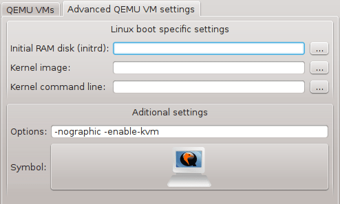
- Qemu additional parameters: -nographic -enable-kvm
1. Installation Steps
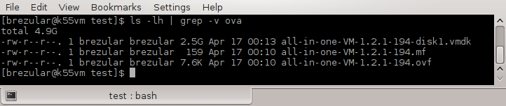
Extract image from the zip file.
$ unzip TiMOS-SR-12.0.R6-vm.zip
$ cd vm/7xxx-i386/
Now a virtual disk sros-vm.qcow2 is extracted. To start Qemu virtual machine use the command:
$ /usr/local/bin/qemu-system-x86_64 -m 2048MB -enable-kvm sros-vm.qcow2 -serial telnet:localhost:3366,server,nowait -smp 2
Telnet to a serial port of virtual machine with the command:
$ telnet localhost 3366
Login with username admin and password admin.
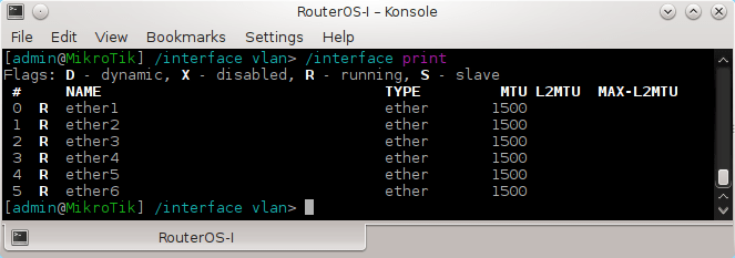
Check cards that are presented presented in a system with the command:
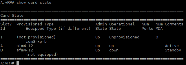
A:vRR# show card state
![Picture1-Timos_Cards]()
Picture 1 - Card iom3-xp-b is Detected but not Provisioned
Card IOM3-XP-B is equipped in slot 1 of chasis but it is not provisioned. Thus we mustto provision it for the slot 1.
*A:vRR# configure card 1 card-type "iom3-xp-b"
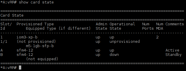
![Picture2-Provisioned_iom3-xp-b_Card]()
Picture 2 - Card iom3-xp-b Provisioned in Slot 1
Card iom3-xp-b accepts up to two Media Dependent Adapters (MDAs). There is a one unprovisioned module m5-1gb-sfp-b equipped in port one of card iom3-xp-b that provides five Ethernet interfaces. We have to specify slot and mda type and save configuration.
*A:vRR# configure card 1 mda 1 mda-type "m5-1gb-sfp-b"
*A:vRR# admin save
Now we can connect vSIM virtual machine to connect to GNS3.
2. Connecting vSIM to GNS3
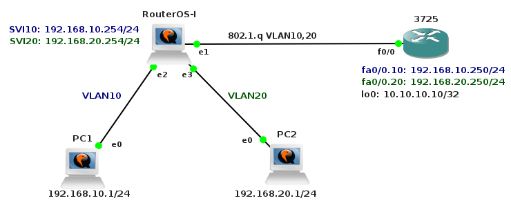
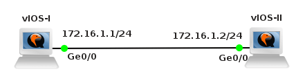
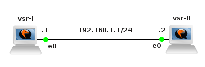
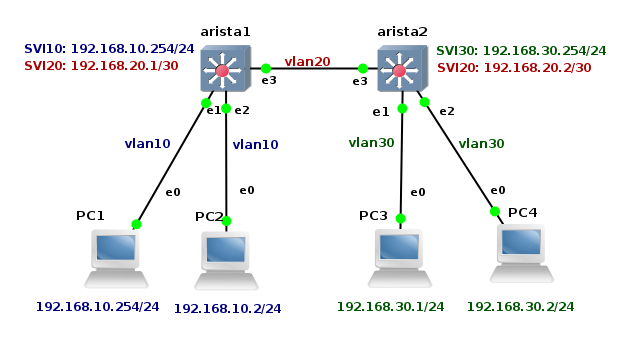
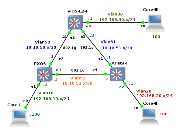
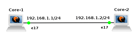
We are going to create a simple topology in order to check network connectivity between vSIM ports and Core Linux hosts.
![Picture3-Testing_Topology]()
Picture 3 - Port Connectivity Testing Topology
They are six Linux Core hosts connected to the ports of virtual service router. A table mapping vSIM ports and how they are presented in TiMOS configuration is following:
Timos ----- vSIM ports
bof ----------- eth0
1/1/1 --------- eth1
1/1/2 --------- eth2
1/1/3 --------- eth3
1/1/4 --------- eth4
1/1/5 --------- eth5
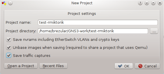
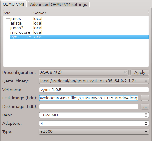
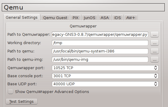
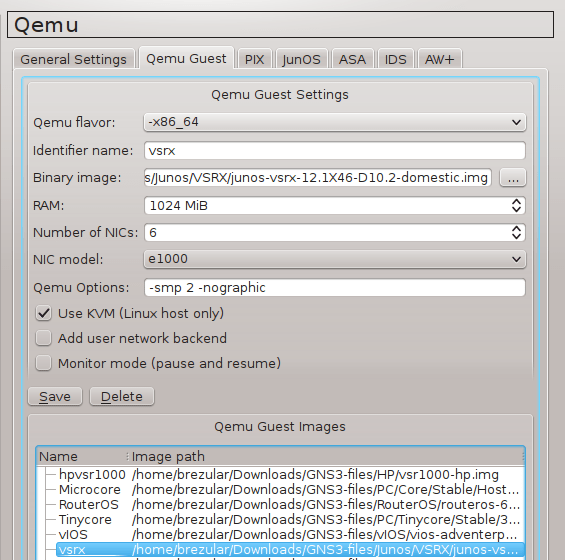
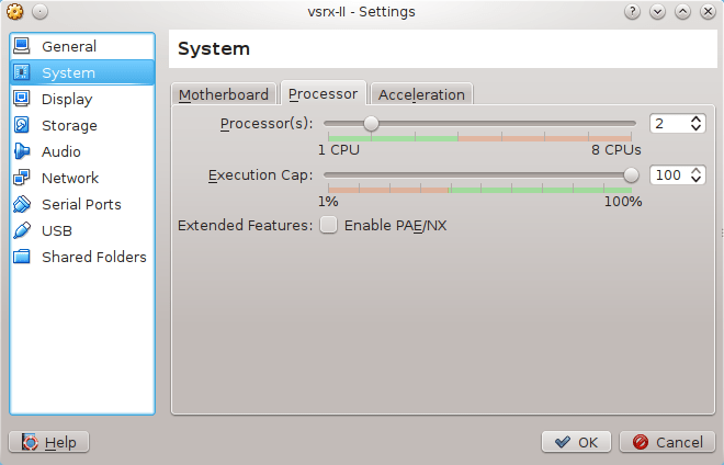
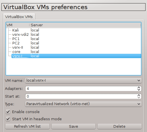
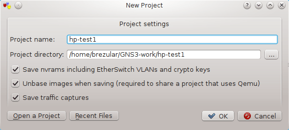
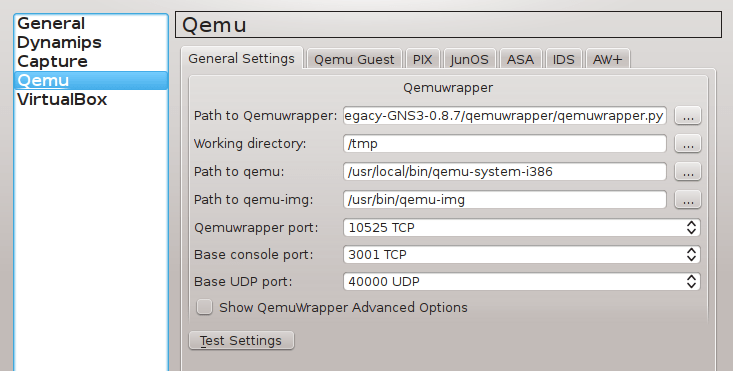
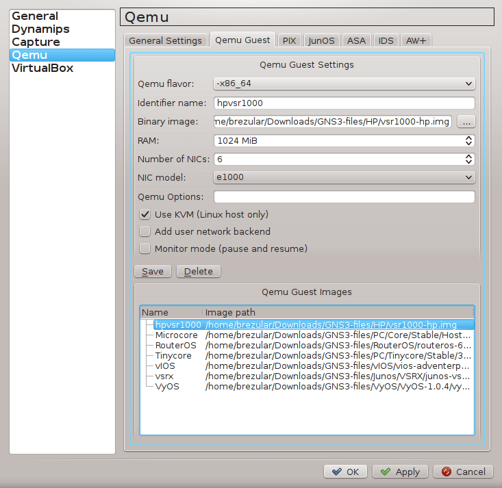
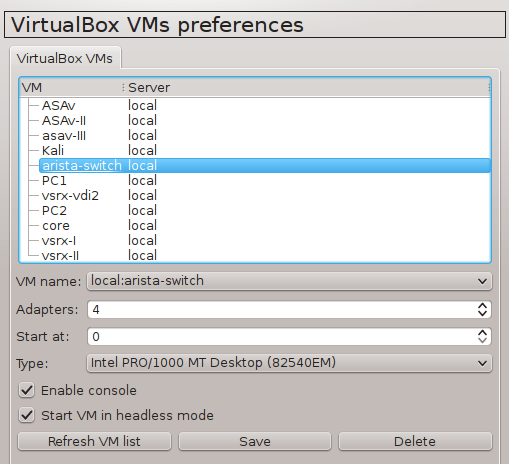
2.1 Configure GNS3 Qemu VMs Preferences
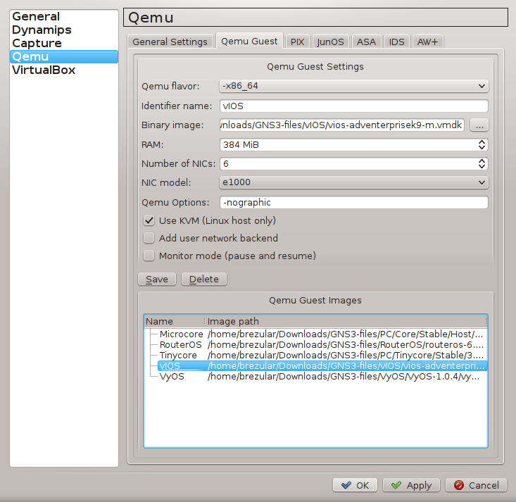
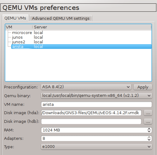
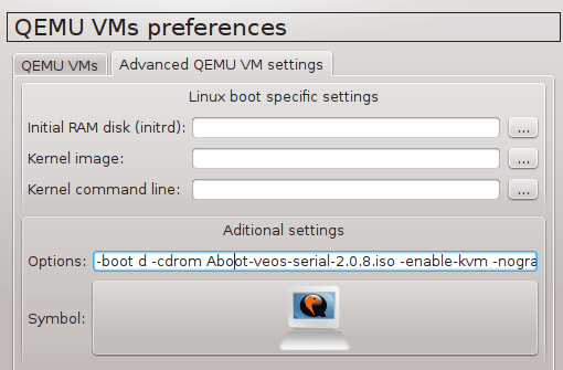
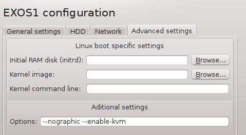
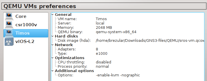
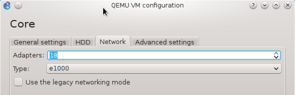
Navigate to Edit -> Preferences -> QEMU VMs and configure VM parameters according to the picture below.
![Picture4_vSIM_GNS3_QEMU_VM_Configuration]()
Picture 4 - GNS3 Qemu VM Configuration
2.2 IP Address Configuration for Control Proccessor Module (CPM) Management Ethernet Interface
The interface eth0 is connected to CPM management interface. Use BOF command-line interface (CLI) to configure IP address for CPM interface.
*A:vRR# bof address 10.10.10.1/24
Save bof configuration.
*A:vRR# bof save
2.3 Linux Core Configuration - PC0
Login with username tc. Password is not set.
tc@box:~$ sudo su
root@box:~# echo "ifconfig eth0 10.10.10.2 netmask 255.255.255.0" >> /opt/bootlocal.sh
root@box:~# echo "route add default gw 10.10.10.1" >> /opt/bootlocal.sh
root@box:~# /opt/bootlocal.sh
root@box:~# /usr/bin/filetool.sh -b
2.4 IP Address Configuration for Port 1/1/1
*A:vRR# configure port 1/1/1 no shutdown
*A:vRR# configure router interface "PC1" address 192.168.1.1/24
*A:vRR# configure router interface "PC1" port 1/1/1
Note: The interface Ethernet 1 is represented by the port 1/1/1 in TiMOS configuration.
2.5 Linux Core Configuration - PC1
tc@box:~$ sudo su
root@box:~# echo "ifconfig eth0 192.168.1.2 netmask 255.255.255.0" >> /opt/bootlocal.sh
root@box:~# echo "route add default gw 192.168.1.1" >> /opt/bootlocal.sh
root@box:~# /opt/bootlocal.sh
root@box:~# /usr/bin/filetool.sh -b
2.6 IP Address Configuration for Port 1/1/2
*A:vRR# configure port 1/1/2 no shutdown
*A:vRR# configure router interface "PC2" address 192.168.2.1/24
*A:vRR# configure router interface "PC2" port 1/1/2
2.7 Linux Core Configuration - PC2
tc@box:~$ sudo su
root@box:~# echo "ifconfig eth0 192.168.2.2 netmask 255.255.255.0" >> /opt/bootlocal.sh
root@box:~# echo "route add default gw 192.168.2.1" >> /opt/bootlocal.sh
root@box:~# /opt/bootlocal.sh
root@box:~# /usr/bin/filetool.sh -b
2.8. IP Address Configuration for Port 1/1/3
*A:vRR# configure port 1/1/3 no shutdown
*A:vRR# configure router interface "PC3" address 192.168.3.1/24
*A:vRR# configure router interface "PC3" port 1/1/3
2.9 Linux Core Configuration - PC3
tc@box:~$ sudo su
root@box:~# echo "ifconfig eth0 192.168.3.2 netmask 255.255.255.0" >> /opt/bootlocal.sh
root@box:~# echo "route add default gw 192.168.3.1" >> /opt/bootlocal.sh
root@box:~# /opt/bootlocal.sh
root@box:~# /usr/bin/filetool.sh -b
2.10 IP Address Configuration for Port 1/1/4
*A:vRR# configure port 1/1/4 no shutdown
*A:vRR# configure router interface "PC4" address 192.168.4.1/24
*A:vRR# configure router interface "PC4" port 1/1/4
2.11 Linux Core Configuration - PC4
tc@box:~$ sudo su
root@box:~# echo "ifconfig eth0 192.168.4.2 netmask 255.255.255.0" >> /opt/bootlocal.sh
root@box:~# echo "route add default gw 192.168.4.1" >> /opt/bootlocal.sh
root@box:~# /opt/bootlocal.sh
root@box:~# /usr/bin/filetool.sh -b
2.12 IP Address Configuration for Port 1/1/5
*A:vRR# configure port 1/1/5 no shutdown
*A:vRR# configure router interface "PC5" address 192.168.5.1/24
*A:vRR# configure router interface "PC5" port 1/1/5
2.13 Linux Core Configuration - PC5
tc@box:~$ sudo su
root@box:~# echo "ifconfig eth0 192.168.5.2 netmask 255.255.255.0" >> /opt/bootlocal.sh
root@box:~# echo "route add default gw 192.168.5.1" >> /opt/bootlocal.sh
root@box:~# /opt/bootlocal.sh
root@box:~# /usr/bin/filetool.sh -b
2.14 Additional Configuration
Hostname
A:vRR# configure system name Timos-I
Admin Password
*A:Timos-I#password
Save Configuration
*A:Timos-I# admin save
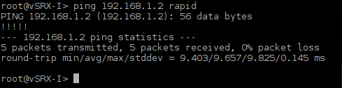
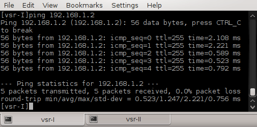
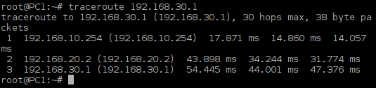
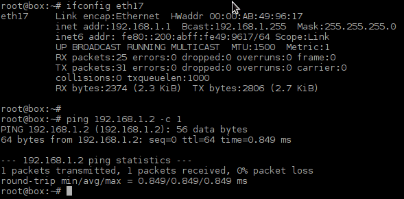
2.15 Testing Connectivity between vSIM Ports
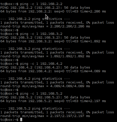
Login to PC1 and ping IP address of PC2, PC3, PC4 and PC5. As the hosts have default gateway configured, ping should be successful.
![Picture5_Testing_COnnectivity_Between_vSIM_Ports]()
Picture 5 - Testing Connectivity Between vSIM Ports
3. Testing OSPF MD5 Authentication Between Cisco CSR1000v and Alcatel-Lucent vSIM
In this lab we will focus on configuration and testing authentication in OSPF routing protocol running on Cisco CSR1000v router and Alcatel-Lucent virtual simulator.
Installation and configuration of Cisco Cloud Service Router CSR1000v in GNS3 is explained here.
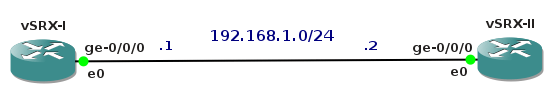
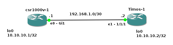
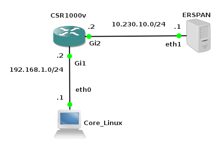
![Picture6-OSPF_Testing_Topoly]()
Picture 6 - OSPF Authentication Testing Topology
Note: A Link labeled as eth0 and connected to the first available port on CSR1000v is presented as interface GigabitEthernet 1 in CSR1000v configuration. Similarly, a link labeled as eth1 and connected to the second available port on Alcatel-Lucent vSIM is presented as port 1/1/1 in TiMOS CLI.
3.1 OSPF Configuration on CSR1000v
Password is set to lab123 and it must match between two OSPF neighbors.
Router>enable
Router#conf t
Router(config)#interface gigabitEthernet 1
Router(config-if)#ip address 192.168.1.1 255.255.255.0
Router(config-if)#ip ospf network point-to-point
Router(config-if)#ip ospf authentication message-digest
Router(config-if)#ip ospf message-digest-key 1 md5 lab123
Router(config-if)#no shutdown
Router(config-if)#exit
Router(config)#hostname CSR1000v-I
CSR1000v-I(config)#ip routing
SR1000v-I(config)#interface loopback 0
CSR1000v-I(config-if)#ip address 10.10.10.1 255.255.255.252
CSR1000v-I(config-if)#no shutdown
CSR1000v-I(config)#router ospf 1
CSR1000v-I(config-router)#router-id 1.1.1.1
CSR1000v-I(config-router)#network 10.10.10.2 0.0.0.0 area 0
CSR1000v-I(config-router)#network 192.168.1.0 0.0.0.3 area 0
Note: If you want to enable MD5 authentication for all interfaces in area 0, add the command:
CSR1000v-I(config-router)#area 0 authentication message-digest
3.2 OSPF Configuration Alcatel-Lucent Virtual Simulator
*A:vRR#configure system name Timos-I
*A:Timos-I# configure port 1/1/1 no shutdown
*A:Timos-I# configure router interface toCSR address 192.168.1.2/30
*A:Timos-I# configure router interface "toCSR" port 1/1/1
*A:Timos-I# configure router interface lo0 address 10.10.10.2/30
*A:Timos-I# configure router interface "lo0" loopback
*A:Timos-I# configure router ospf router-id 2.2.2.2
*A:Timos-I# configure router ospf area 0.0.0.0 interface "toCSR" interface-type point-to-point
*A:Timos-I# configure router ospf area 0.0.0.0 interface "lo0"
A:Timos-I# configure router ospf area 0.0.0.0 interface "toCSR" authentication-type message-digest
*A:Timos-I# configure router ospf area 0.0.0.0 interface "toCSR" message-digest-key 1 md5 "lab123"
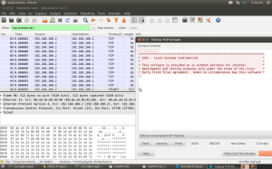
Note: vSIM has the maximum transmission unit (MTU) set to 8936 Bytes for Ethernet interfaces by default. The default MTU value for CSR 1000v Ethernet interfaces is 1500 Bytes. In order to establish OSPF neigborship between two routers, MTU must match on both sides of link. For this reason we must configure MTU 1500 Bytes for vSIM port 1/1/1.
However as it is shown from the debug command enabled on Cisco, CSR 1000v continues complaining about smaller size of MTU. The MTU received in OSPF packets from the neighbor vSIM router is 1486 Bytes. It causes that routers are not fully adjacent and they stay in EXCHANGE neighbor state.
CSR1000v-I#debug ip ospf adj
*Dec 16 19:17:24.428: OSPF-1 ADJ Gi1: Rcv DBD from 2.2.2.2 seq 0x1E opt 0x42 flag 0x7 len 32 mtu 1486 state EXCHANGE
*Dec 16 19:17:24.428: OSPF-1 ADJ Gi1: Nbr 2.2.2.2 has smaller interface MTU
Changing MTU parameter to 1514 Bytes for Ethernet port 1/1/1 on vSIM helps to solve the issue.
*A:Timos-I# configure port 1/1/1 ethernet mtu 1514
3.3 OSPF MD5 Authentication Trobleshooting
We are going to check if routers are fully adjacent and if OSPF routes are presented in both routers's routing tables.
3.3.1 Checking OSPF on CSR1000v
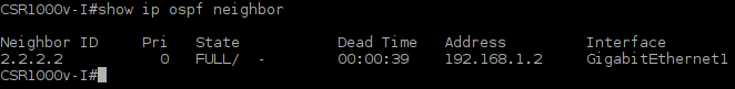
CSR1000v-I#show ip ospf neighbor
![Picture7-OSPF_Neigborship_Cisco]()
Picture 7 - Full OSPF Neigborship Established
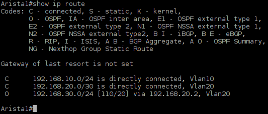
CSR1000v-I#show ip route
![Picture8_CSR1000v_Routing_Table]()
Picture 8 - Routing Table of Cisco CSR1000v
3.3.2 Checking OSPF on Alcatel-Lucent vSIM
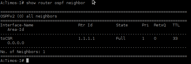
A:Timos-I# show router ospf
![Picture9-OSPF_Neigborship_vSIM]()
Picture9 - OSPF Neighbor 1.1.1.1 presented in TiMOS CLI
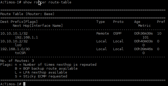
A:Timos-I# show router route-table
![Picture10_vSIM_Routing_Table]()
Picture 10 - Routing Table of Alcatel-Lucent vSIM
End.
References:
http://echorequest.info/
http://labelswitched.blogspot.sk/2013/02/understanding-alcatel-lucent-ipv4.html
http://labelswitched.blogspot.sk/2013/02/ospf-configuration-comparison.html